JMRI: Simple Signal Logic Example
Don't use the Simple Signal Logic (SSL) Tool when you have already built Signal Masts and the more advanced Signal Mast Logic in the same Panel/Configuration file.
This page provides an example of using the JMRI Simple
Signal Logic (in short: SSL) to control Signals Heads
connected to a Digitrax SE8C board. This also works for other
types of single head hardware signals, including LEDs
connected to stationary decoders, C/MRI systems, etc.
Please try our ready-to-use example
as a starter for setting up your own
SSL.
Modeling railroad signaling on a layout can be done in many different ways, ranging from "stoplights" to complete emulation of a particular prototype's signaling rule book. For more information on the various possibilities, please see the JMRI Signaling help page.
Predefined example
A predefined SSL example is provided in the JMRI installation (see the download page for information on downloading). To use this example:
- Start the PanelPro program, and select "Preferences..." from the Edit menu (from the PanelPro menu on OS X). On the pane that opens, click Connections at left and then select "Digitrax" as the System Manufacturer and "LocoNet Simulator" as the System Connection. Click the Save button at the bottom left of the Preferences pane and quit PanelPro. This will let you use the example (which uses LocoNet addresses for Signal Heads, Turnouts and Sensors) even when your computer is not connected to a layout of any kind.
- Restart the PanelPro program.
- From the "Panels" menu, select "Open Panels..." and
navigate to the file "SE8cSignalExample.xml" in the
JMRI/xml/layout/
directory. Note that you may have to look around for this
file; it's in the same place that you installed the
program.

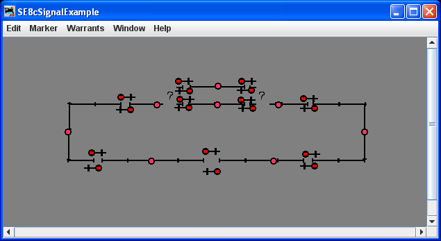
- You should now see a simple schematic Panel for a
layout consisting of a loop of track and one passing siding
(like the non-functioning image to the right; click to
enlarge).
Because there's no connection to a real layout, the status of the Sensors and Turnouts isn't initially known. Our example shows this by displaying the Sensor icons as Red, and the Turnout icons as [?] meaning "not connected either way". Since the Simple Signal Logic isn't sure yet whether Blocks are occupied nor how Turnouts are set, it shows a "Red" Appearance on all Signal Heads.
You can click on your Panel icons to change the occupancy and turnout status, or use another tool (e.g. the Turnout Table) to do that.
Click on each of the Turnout icons to set them "Closed". Click on the Sensor icons to set them "Unoccupied", which is shown as a grey circle ("Occupied" would be indicated by a yellow circle).
- The display should now look like the image to the
right.
 Both signals on the
passing siding are Red, as the Turnouts are thrown against
them. All the signals on the mainline show a Green
Appearance.
If you "hover" the cursor over an item on your Panel, a tooltip will pop up with information about the item. For example, a Turnout might pop up "Turnout 1 (LT1)". LT1 is the "System Name" for that Turnout. In this case, it means "LocoNet Turnout with address 1". "Turnout 1" is the "User Name", which can be anything you want it to be as long as it is unique on your Panel. You can edit these from the "Turnout Table" accessed from the Tools > Tables > Turnouts menu.
Signal Heads and Sensors are identified using similar names (see the JMRI help page on System Names and Naming). - You can now click on the Sensor icons to learn how the
Signals react to the presence of a train. For example, the
image to the right shows a train entering the passing
siding from the left side. It's about to encounter a Yellow
signal upon entering the siding, which tells it to be
prepared to stop for a Red signal at the far end of the
siding.
 Note that the rear of
this train is protected by a Red signal, which in turn is
protected by a Yellow signal in the preceding Block.
Another train is just leaving onto the main going to the
right.
 - If you're interested in how the program would
communicate with a real Digitrax SE8c signaling board, you
can open the "Monitor LocoNet" tool from the LocoNet
menu.
In the pane that opens, you will see that clicking on a Turnout icon sends a LocoNet message to move that Turnout. Clicking on a Sensor icon sends a message as if a BDL16 sensor channel had seen a change in occupancy. If either of those messages results in a change to the signals, the program will send messages to the corresponding SE8c channels to change their output to match. For example, when the train in the previous image enters the block on the right side (Block 1), the messages are:Sensor LS1 (Block 1) is Hi. (BDL16 #1, DS1; DS54/64/SE8c #1, AuxA/A1/DS01) Requesting Switch at LT285 () to Thrown (output On). Requesting Switch at LT291 () to Thrown (output On). Requesting Switch at LT282 () to Thrown (output On).
These three switch messages set Signal Heads 4C, 5B and 4A to Red, Red and Yellow respectively. - To learn how signals are configured in SSL, open the
"Simple Signal Logic" item in the Tools menu.
 In the pane that opens,
enter a Signal (Head) Name, e.g. "Section 5A", in the top
text field and hit the Return key. You should get
something like the image to the right (click to enlarge).
"Section 5A" is the name of the Signal (Head) protecting
Turnout "LT2", the right-hand entrance to the passing
siding.
- It is defined here as an "On Facing-Point Turnout" signal.
- It protects Sensor "LS7" by turning Red when the Sensor detects a train in the Block monitored by LS7.
- It watches the status of Turnout "LT2".
To Protect Signal: When Turnout LT2 is "Closed", signal "Section 5A" will be Yellow when Signal Head LH261, located on the mainline between the turnouts, is Red.
And Protect Signal: When Turnout LT2 is "Thrown", signal "Section 5A" will be Yellow when Signal Head LH263 at the entrance to the passing siding is Red. - The "With Flashing Yellow" checkbox isn't selected in our example, but if it was, signal "Section 5A" would protect a Yellow signal further on by displaying a Flashing Yellow.
- If you check the "Distant Signal" box, the Signal Head you're controlling here is programmed to show the same or a more restrictive Appearance as the next signal, instead of possibly one faster. Instead of showing Yellow before a Red, it will show a Red.
Setting up your own example
The complete set of steps involved in creating this example are:- Launch and configure the PanelPro application. Restart
it to have your preferences take effect.
For more information on launching and configuring PanelPro, please see the PanelPro help page. - Tell the program about your Sensors:
- From the Tools menu, open the "Tables" > "Sensors" tool.
- If you have a Digitrax DCC system with your occupancy detectors connected to LocoNet, just power the track Off and On using either a DT-series throttle or the "Power Control..." pane from the Tools menu. PanelPro will capture all sensor addresses from the resulting LocoNet traffic.
- For layouts with a different System Connection, use the "Add..." button at the bottom of the Sensor Table to create the needed sensors.
- Save your work by selecting "Store Panels..." from the "Panels" menu, typing a filename, and hitting "Save Panels". (You might want to do this often!)
- Tell the program about your computer-driven Turnouts:
- From the Tools menu, open the "Tables" > "Turnouts" tool.
- If you have a Digitrax DCC system, just throw or close each Turnout from a throttle. PanelPro will capture the Turnout addresses from the resulting LocoNet traffic.
- You can also use the "Add..." button on the Turnout Table to open a pane to enter new Turnouts.
- The "Turnout Control..." pane, found in the Tools menu, also creates a new Turnout entry for every turnout address you operate.
- If you have Signal Heads connected to "turnout-type" outputs, tell the program about those Turnout addresses too (SE8C users skip this step).
-
Tell PanelPro
how your Signal Heads are addressed:

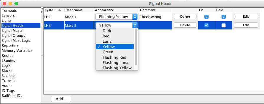
- From the PanelPro Tools menu, open the Tables > Signals > Signal Heads tool.
- Click the "Add..."
button at the left bottom of the table to pop a pane.
At the top are several choices for your type of Signal
Head driver:
- Triple Output
- A Signal Head Connection Type with
red/yellow/green lights that are driven by three
separate outputs. The outputs are driven by JMRI
turnout logic, and appear in the Turnout Table.
To configure one of these, enter the name you want to give it (typically something like "IH2"), and the address numbers of the three outputs that drive the lamps (like "258" etc.). - Double Output
- A Signal Head Connection Type with lights that
are driven by two output connections. The two
outputs drive red and green lights separately;
PanelPro will turn them both On to make yellow. The
outputs are driven by JMRI turnout logic, and
appear in the Turnout Table.
To configure one of these, enter the name you want to give it (typically something like "IH2"), and the address numbers of the two outputs that drive the lamps (like "258" etc.). - SE8c 4 Aspect
- This Connection Type is for Signal Heads driven
by a Digitrax SE8c decoder.
Enter the lower of the two Turnout addresses that this Signal Head responds to. For example, if it's the first Signal Head on your first SE8c board, you can control it by setting Turnouts 257 and 258 with your throttle. Enter "257" in the Turnout Number box on the pane.
Note: The SE8c board should be configured so that the "4th aspect" is "Dark"; JMRI will handle any flashing that's needed. - And many more...
- Other signal driver options are "DCC Signal
Decoder" and "Acela", among many others (you may
have to scroll up or down to see them all).
See the Signal Heads help page for more information an each.
- Configure your signaling logic using the Simple Signal
Logic (SSL) Tool.
Open the "Simple Signal Logic" tool from the "Tools" menu. You should get a pane with a number of fields:
- In the top box, enter the name of the Signal Head you want to configure.
- The radio buttons below that select one of four
possible uses for this signal:
- "On Single Block" - this signal protects one end of a straight through block, with no signaled turnouts
- "Main Leg of (trailing-point) Turnout" - this signal is along the main route through a turnout, which is defined as the direction taken by trains when the turnout is "Closed". It's protecting the frog of the turnout so that trains will stop before running through a turnout set against them.
- "Diverging Leg of (trailing-point) Turnout" - this signal is along the diverging route through a turnout, which is defined as the direction taken by trains when the turnout is set to "Thrown". It's protecting the frog of the turnout so that trains will stop before running through a turnout set against them.
- "On Facing-Point Turnout" - this signal is protecting the points-end of a turnout. Depending on whether the Turnout you watch is "Thrown" or "Closed", the train will take one of two different routes, and the Signal will protect different next Blocks, which you fill in next.
- If you want the Signal Head to go Red when a Sensor shows Occupied (sensor active), enter the Sensor Name in the next box.
- If this signal is protecting travel in the trailing point direction through a turnout, you can have the Signal Head show Red if the turnout is thrown against the train. To do this, enter the Turnout Name to be monitored in the 3rd box, and select whether the Signal Head should be Red when the Turnout is either Thrown or Closed.
- If you want multi-block logic, e.g. Absolute Block
Signaling "Light", enter the name of the following
Signal Head in the last box. When that Signal Head
shows Red, the one you're now configuring will be set
to Yellow to warn the engineer that the train must be
able to stop at the next signal.
If you'd like to give an additional warning, check the "With Flashing Yellow" checkbox. In that case, the signal before a Red will show Yellow, and the signal before that Yellow will show a Flashing Yellow.
We suggest you use the newer Aspect Based Signaling instead of SSL for any more complex setup. - Once you've set the options, click "Apply". You can use this form repeatedly to enter as many as you'd like, each with it's own unique name of course.
- Once you save your work by selecting "Store Configuration and Panels To File..." from the File menu, you're done!
Now try out your Simple Signal Logic by operating your
layout.
Although it's a lot less fun than actually running the
layout, you can also test your Simple Signal Logic by
changing Turnout and Sensor states on the computer itself.
Just click on the status information in one of the Tables to
change it. For example, if Turnout "LT23" is showing "Thrown"
in the Turnout Table, click on that word to change it to
"Closed". The signal icon will update to the new
Appearance.
You can create a small Control Panel to do this graphically. For more info on how to do that, see the Panels help page.
Back to Simple Signal Logic help page.
Located at en\html\tools\signaling\
