Hardware Support: Chubb C/MRI
This documentation discusses how JMRI may be used with C/MRI, and how to get started with connecting a C/MRI system to JMRI. It assumes a basic knowledge of JMRI (as documented on this JMRI web site), and some familiarity with C/MRI. It is highly recommended that C/MRI users have access to Bruce Chubb's C/MRI User Manual, Version 3.0, because it contains detailed hardware documentation not available elsewhere. Since you don't need to write the control software for your computer if you're using JMRI with your C/MRI system, you can skip over computer programming details when consulting the C/MRI User Manual. Excellent, detailed descriptions for various types of signaling systems and model railroad layout device controls are presented in Dr. Chubb's manuals.
The CMRInet protocol definition is published on the NMRA web site under the
Standards and Recommendations Section, Layout Control Specifications:
LCS-9.10 C/MRI Introduction v1.0 (2014.12.01) and LCS-9.10.1 CMRInet v1.1 (2014.12.01).
https://www.nmra.org/sites/default/files/standards/sandrp/Other_Specifications/lcs-9.10.1_cmrinet_v1.1.pdf
Note: C/MRI and CMRI (without the slash) are used interchangeably. The C/MRI communication protocol is referred to as CMRInet.
- The documentation below is divided into sections; for easy access click an item in this list:
- Hardware Support: Chubb C/MRI
- Establishing a C/MRI System Connection
- Managing Nodes
- Configuring C/MRI Nodes
- Adding a Node Definition
- Creating a SMINI Node Definition
- Creating a USIC/SUSIC Node Definition
- Creating a CPNODE Node Definition
- Editing a Node Definition
- C/MRI Input and Output Bits
- Forming a JMRI System Name for a C/MRI Bit
- Creating a Sensor Input
- Creating a Turnout Output
- Turnout Control Options
- Creating a Light Output
- CMRInet Network Management Tools
- Listing C/MRI Bit Assignments
- Diagnostics
- CMRInet Network Connections
- Using An Ethernet Network Connection
- Running JMRI when disconnected from your C/MRI system
- PanelPro Signaling Example Using C/MRI
- JMRI Help
- Third Party info
- Supported Hardware
Limitations
Original Chubb IBEC and UBEC interfaces for older PC system buses (ISA, PCI) are not supported.
Introduction to C/MRI on JMRI
C/MRI is a system of digital input and digital output lines that can be used to connect a computer to a model railroad layout, allowing computer monitoring and control of various things of the layout. The digital input/output device is called a node and connects to the computer using a simple 4-wire serial network cable.
There are three types of C/MRI nodes; USIC/SUSIC, SMINI, and cpNode. The USIC/SUSIC and SMINI are Classic nodes. The cpNode and other Open Source/DIY offerings, which comply with the CMRInet protocol, are referred to as Open Source Nodes (OSN).
The SUSIC (Super Universal Serial Interface Card) and USIC (Universal Serial Interface Card) are serial controller boards for a large digital I/O systems. A motherboard supports up to 32 digital input and digital output cards, with either 24 or 32 input or output lines per card. The USIC is an older version of the SUSIC.
The SMINI (Super Mini-node) card is a stand-alone serial node providing a fixed 24 input lines and 48 output lines.
The CPNODE (cpNode) is a standalone serial node which provides 16 to 144 input and output lines. The cpNode uses an Arduino Leonardo style microprocessor and is an Open Source Node (OSN).
A number of hardware interface boards are available as part of C/MRI. They all connect to your computer via an SMINI, a SUSIC/USIC, or cpNode. For example, C/MRI's DCCOD occupancy detector board connects to an input port on a node.
Layouts which use C/MRI will commonly have several SMINI's located at different places on the layout, and perhaps one or two SUSIC's located at CTC panels. cpNodes are small physical footprint nodes, which can be distributed around a layout to provide connection to devices clustered in an area. All C/MRI node types may coexist and interoperate within a CMRInet network.
C/MRI is not a train control system. You may run C/MRI with a DCC train control system (such as Digitrax, NCE, or Lenz) or with a DC train control system. And you can use JMRI with your C/MRI system whether you are using DCC or DC to control your trains. If you are controlling your trains with a system that JMRI supports, you can connect your C/MRI system and your train control system to JMRI simultaneously, each with its own serial input line into your computer.
Most C/MRI users who use JMRI run with connections to both their C/MRI and their train control system. There are many advantages to doing so. JMRI allows you to "mix and match" how you control and monitor things on your layout. For example, you can switch your Turnouts (track switches) using static decoders on your train control system, and simultaneously use C/MRI inputs to provide Turnout Feedback to JMRI. JMRI is designed to make both connected systems work smoothly together.
JMRI software consists of a large library of functions divided into 1) a system specific part, with many subparts, each of which communicates with one supported hardware system, like C/MRI, in a system specific way, and 2) a system-independent part where most of the features of JMRI are implemented. So, for example, if the user does something (perhaps setting a route) to cause JMRI to throw a Turnout (track switch), that user action will occur in the system-independent part of the software, and then JMRI will send out the actual command via the system-dependent part appropriate to the hardware system controlling the particular Turnout thrown. JMRI is designed so that features are implemented in the system-independent part as much as possible, with JMRI using system-dependent subparts only when really necessary. Access to system-independent features is via the main JMRI menus, such as the Tools menu.
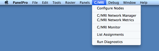
Access to system-dependent features is via a menu titled for the hardware system supported; C/MRI specific features are accessed via the C/MRI menu from the PanelPro main screen.
JMRI presents itself to users via several application front ends, each focusing on a type of use, but all based on the same underlying software library. PanelPro is the JMRI application that focuses on layout automation, signaling, and CTC panels. PanelPro is the application most often used with C/MRI, and is the one used in the examples below. Since all JMRI applications use the same library, it is possible to run a panel from DecoderPro, or even program a DCC decoder from PanelPro. The popular DecoderPro application focuses on programming DCC decoders.
JMRI libraries have built-in support for C/MRI serial hardware using the SUSIC/USIC, SMINI, and cpNode. Each SUSIC/USIC, SMINI, or cpNode is a serial node capable of communicating independently with a computer via serial I/O. Several C/MRI nodes may be connected together using the RS-485 communication protocol in a daisy chain configuration, so that only one serial line into your computer is required. For this to work, each node must have a different unique address set into the address switches on its board or defined in the cpNode Kernel sketch.
Each node (SUSIC/USIC, SMINI, or cpNode) needs to receive an initialization string before it can communicate with a computer. JMRI will automatically create and transmit the required initialization string when it starts up, but to make this possible, you need to tell JMRI the details of how your C/MRI hardware is set up. The process of doing this is called "configuring" your C/MRI Node (see below). If you daisy chain several C/MRI nodes, you will need a C/MRI RS-232 to RS-422/485 conversion card or USB to RS-422/485 interface between the RS-422/485 bus connecting the cards and the RS-232 serial port to connect to your computer. If your computer does not have an RS-232 serial port (most newer computers don't), you can connect to a USB computer port with a USB-to-serial adapter.
C/MRI inputs are defined in JMRI as 'Sensors', and C/MRI outputs can be defined as JMRI 'Turnouts' or JMRI 'Lights' (see below). Note that C/MRI inputs and outputs are sometimes called 'bits', 'pins', or 'lines'; all are equivalent ways to refer to same things.
CMRInet is a polled master/slave system, which means that communicating with C/MRI nodes requires that a "master" computer periodically sends a message to each "slave" node asking it to transmit the status of its' input bits. JMRI begins to poll a node when at least one Sensor has been set up to refer to an input bit on that node. It is this polling action that keeps the network traffic activity LEDs on the nodes flashing at a high rate. JMRI will transmit output data to a particular addressed node to change the state of the defined output bits in the node.
Establishing a C/MRI System Connection
Before C/MRI sensors and turnouts can be defined, a CMRInet system connection needs to be established. This is done from the Preferences window. Note: A CMRInet connection can be a physical hardware connection via a serial hardware interface or a simulated connection.
To create a CMRInet connection, open the Preferences window. Click on Connections in the left selection box.
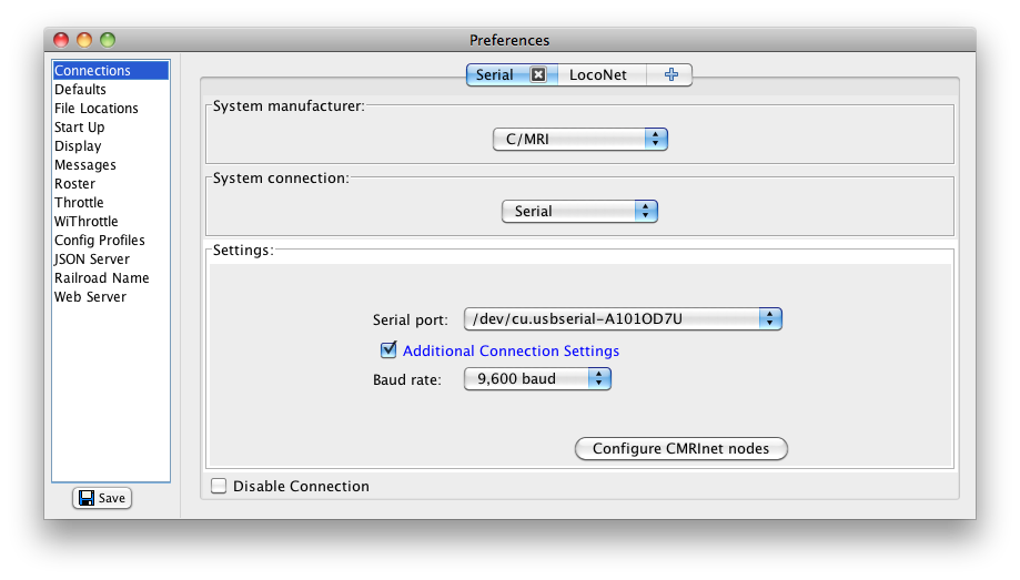
Select C/MRI in the System manufacturer menu popup. Select Serial from the System connection menu popup. Under Settings, select the name of the physical serial port on the computer. Either an RS-232 or USB port can be selected.
Click on Additional Connection Settings, select the network line speed that the C/MRI nodes are configured.
Click Save to create the serial connection. JMRI will present a dialog window asking if you want to restart, Click Yes.
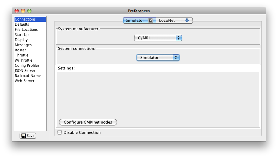
A Simulator connection is very useful if you are creating a PanelPro panel and do not have actual C/MRI hardware in place.
To create Sensor and Turnout table entries, you must have a connection defined to specify the connection system. CMRInet devices use "C" as the default system prefix when creating System Names.
To create a Simulator connection, follow the same steps above and select Simulator for the System connection. Be sure to Save the simulator connection.
A physical and simulator connection may exist at the same time, but only one may be active at a time. Use the Disable Connection checkbox to enable or disable a connection.
Managing Nodes
An SMINI, USIC/SUSIC, or cpNode is called a "node". A node is a point in the CMRInet network where the physical connections for controlled layout equipment is done. Before using C/MRI with JMRI, you must tell JMRI what nodes you have on your system and the configuration of each node.
Each node has a unique node address in the range of 0 to 127. Node addresses are set using switches on the SMINI and USIC/SUSIC boards, or entering the node number into the cpNode software sketch. In the C/MRI manuals, node addresses are called the Unit Address (UA).
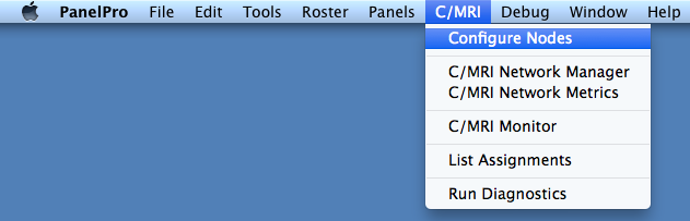
You can add new nodes or update an existing node's configuration by returning to the Preference dialog (Edit > >Preferences...) or by selecting Configure Nodes in the C/MRI menu in the main PanelPro window.
You will need to save your Preferences after making changes to your node configuration. Use the "Save" button in the Preferences window to do this.
Configuring C/MRI Nodes
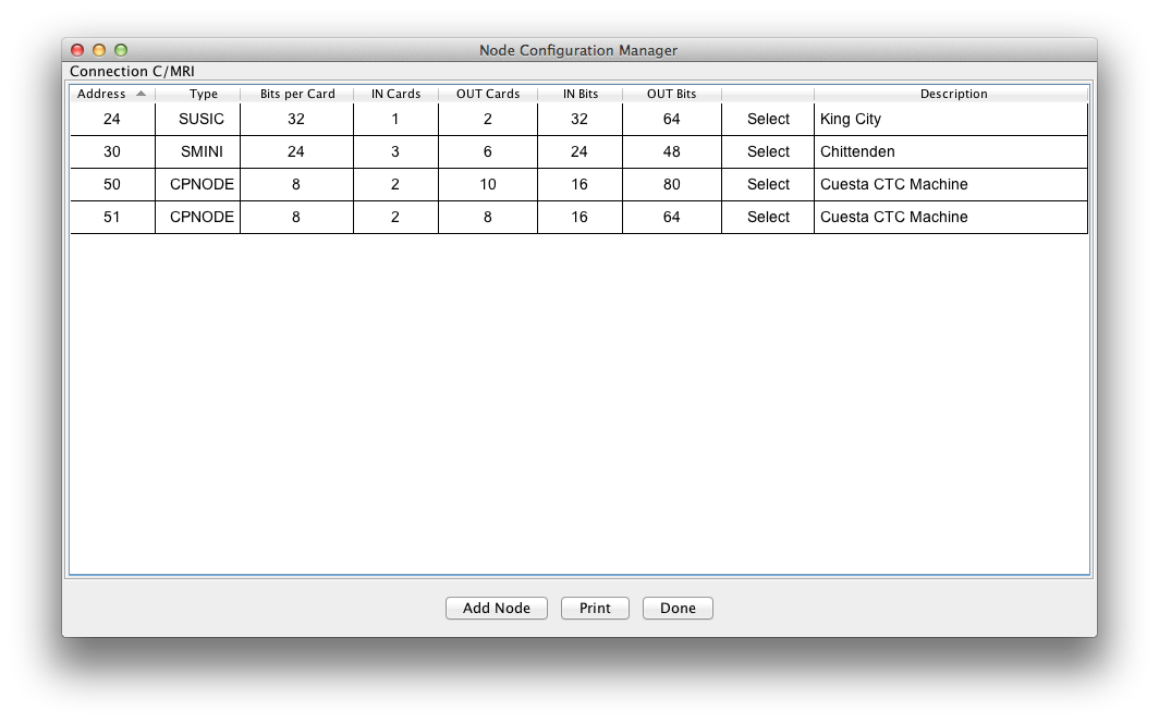
CMRInet nodes are created from the Node Configuration Manager window.
C/MRI nodes require certain information be established for proper operation within the CMRInet network. Each node type has some common parameters, and may have specific parameters for initialization and data port mapping.
To open the Node Configuration Manager window from the PanelPro Main menu and select C/MRI -> Configure Nodes. You may also click on the "Configure CMRInet nodes" button in the Preferences window.
Any existing C/MRI nodes will be displayed by node address. The serial connection name is displayed with additional configuration information for the node. Clicking on any of the column titles will sort the rows in alphanumeric order.
Adding a Node Definition
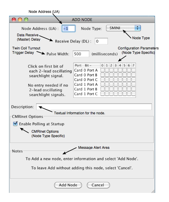
To add a node, click the Add Node button at the bottom of the Node Configuration Manger window. The Add Node window will be displayed.
There are parameters, which need to be entered for every node type. These entries are required and some are common to all C/MRI node types. The example below shows the data fields for an SMINI. See the individual sections for creating the specific node definitions.
Clicking on the Done button will close the Node Configuration Window.
A printed list of configured nodes can be provided by clicking on the Print button.
Creating a SMINI Node Definition
Open the Node Configuration Window from either the Preferences window or from the PanelPro main menu, select CMRI -> Configure Nodes.
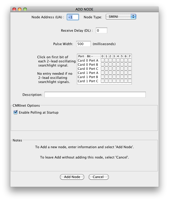
Select SMINI from the Node Type popup menu.
- Enter the node address in the Node Addressfield.
- If required, enter Receive Delay value, otherwise leave as Zero.
- If using twin coil switch motors and a different ON pulse value is required, enter that value, otherwise leave as 500.
- If you are using the Yellow signal aspect feature (2-lead oscillating searchlight) of the SMINI, set the check boxes as needed. See the Chubb documentation on the SMINI for specific details setting up this option.
- The Description field provides a text entry area for a description of the node. An example could be the physical area of the SMINI controlled section on the layout.
- Enable Polling at Startup is checked. This option, when enabled, means polling of the node will start when PanelPro launches. Un-checking the option will prevent the node from being polled at startup.
Click the Add Node button. The entries are checked for valid data, and if any data errors are present, an error message will be displayed in the Alert Message area.
You must do a Save from the Preferences window for nodes which are added.
Creating a USIC/SUSIC Node Definition
Open the Node Configuration Window from either the Preferences window or from the PanelPro main menu, select C/MRI -> Configure Nodes.
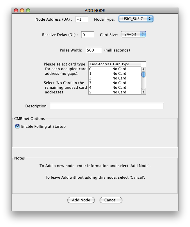
Select USIC_SUSIC from the Node Type popup menu.
- Enter the node address in the Node Address field.
- Set the Card Size from the popup menu. This parameter defines the type of Chubb input (DIN/DIN32) or output (DOUT,DOUT32) cards which are plugged into an I/O motherboard. The USIC/SUSIC card plugs into the motherboard and is the serial interface to the control computer. A card size of 24-bit represent three byte cards (DIN/DOUT) and 32-bit represents four byte cards (DIN32/DOUT32).
- If required, enter Receive Delay value, otherwise leave as Zero.
- Pulse Width is specified when using twin coil switch motors. If a different value is required, enter that value, otherwise leave as 500.
- You need to define the type of card, by cardaddress (set by switches on the card), and whether the card is an input or an output. For each card installed, click on "No Card" and select "Input Card" or "Output Card" for that position on the motherboard. Note that the input and output cards may be in any order, but there must be no empty slots before the one following the last installed card. This is a C/MRI hardware requirement
- The Description field provides a text entry area for a description of the node. An example would be the physical location on the layout.
- Enable Polling at Startup is checked. This option, when enabled, means polling of the node will start when PanelPro launches. Un-checking the option will prevent the node from being polled at startup.
Click the Add Node button. The entries are checked for valid data, and if any data errors are present, an error message will be displayed.
You must do a Save from the Preferences window for nodes which are added, updated, or deleted.
Creating a CPNODE Node Definition
Open the Node Configuration Window from either the Preferences window or from the PanelPro main menu, select C/MRI -> Configure Nodes.
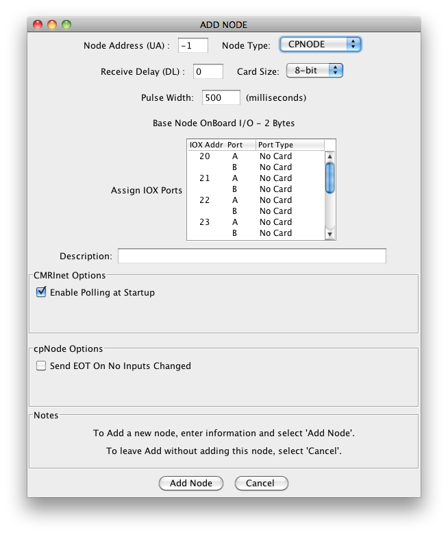
Select CPNODE from the Node Type popup menu.
- Enter the node address in the Node Address field.
- The card size for a CPNODE is 8 bits.
- If required, enter Receive Delay value, otherwise leave as Zero.
- Pulse Width is specified when using twin coil switch motors. If a different value is required, enter that value, otherwise leave as 500.
- You need to define the type of card, by cardaddress (set by switches on the card), and whether the card is an input or an output. For each card installed, click on "No Card" and select "Input Card" or "Output Card" for that position on the motherboard. Note that the input and output cards may be in any order, but there must be no empty slots before the one following the last installed card. This is a C/MRI hardware requirement
- cpNodes can have input/output expanders (IOX16,IOX32) which provide additional I/O data ports. If IOX support has been enabled in the cpNode, select for each defined IOX by board address, the port direction for each card. No Card corresponds to an unused byte in the IOX.
- The Description field provides a text entry area for a description of the node. An example would be the physical location on the layout.
- Enable Polling at Startup is checked. This option, when enabled, means polling of the node will start when PanelPro launches. Un-checking the option will prevent the node from being polled at startup.
- Send EOT On No Inputs Changed is Un-checked. This option, when enabled, means that an Open Source Nodes (OSN) can send and EOT in response to a poll if there has not been a change in input states since the last poll.
Click the Add Node button. The entries are checked for valid data, and if any data errors are present, an error message will be displayed.
You must do a Save from the Preferences window for nodes which are added, updated, or deleted.
Editing a Node Definition
Node configuration parameters may be changed by selecting the Edit function from the Node Configuration Manager window.
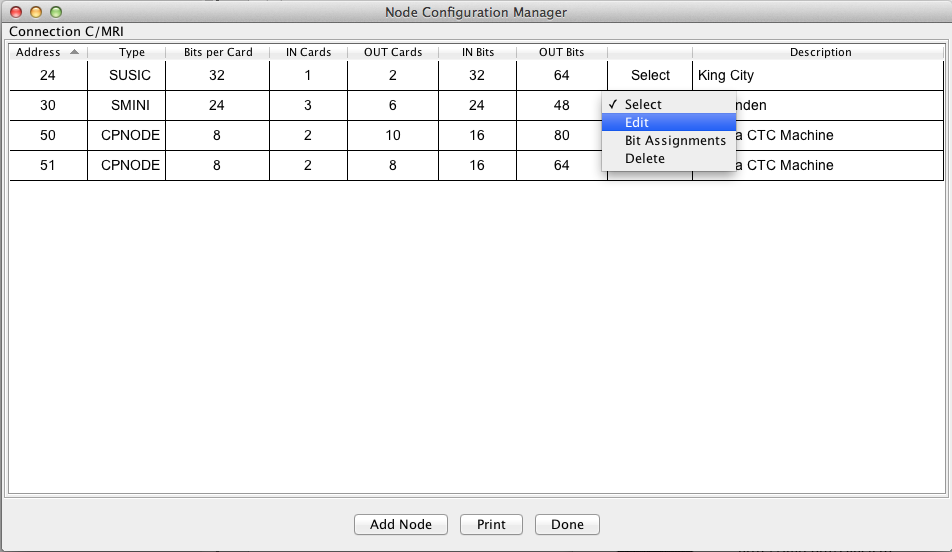
For the node you want to edit, click on the Select popup column for the node, and select Edit.
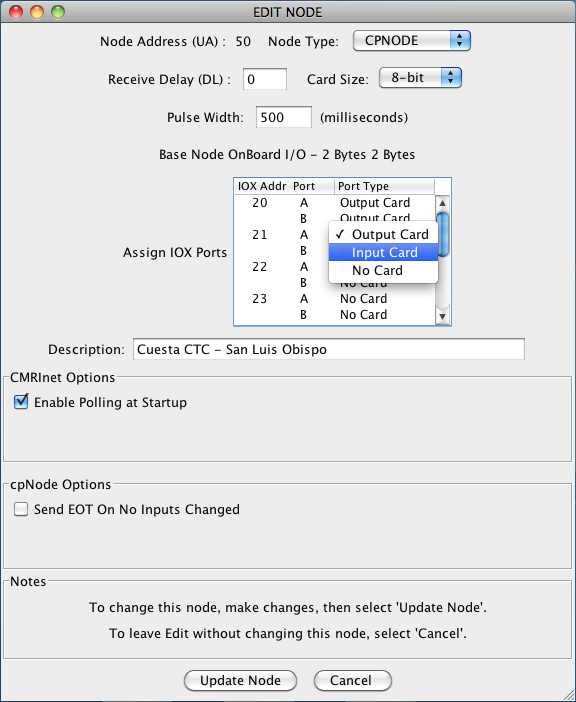
The Edit Node window will open and display the configuration for the selected node. The node address cannot be modified. Make the necessary changes, then click on the Update Node button. If there are any data entry errors, an error message will be shown in the "Notes" section of the window. When you are done editing, click on the Done button to close the window.
You must do a Save from the Preferences window for the update to take effect.
Note: When exiting the Node Configuration Manager and changes were made, a warning dialog will be presented reminding you to save your changes from the Preferences window.
C/MRI Input and Output Bits - JMRI Tables
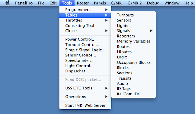
JMRI refers to C/MRI Input bits as Sensors and Output bits as Turnouts or Lights. The definition of Sensors, Turnouts, and Lights is done by adding entries into the appropriate data table. Tables are accessed by selecting from the PanelPro main screen Tools -> Tables -> {table name}
Inputs - Sensor Table
Sensors provide input to JMRI about conditions on the layout; a button is pushed, a block is occupied, etc. When you see a "Sensor" reference, think "input bit" or "input port". A Sensor may be created in a number of ways, including automatically. All JMRI Sensors which have been created may be viewed in the JMRI Sensor Table, which is accessed by selecting Sensor Table in the Tools menu in the main PanelPro window.
A sensor is created by clicking the Add button at the bottom of the Sensor Table. Creating a Sensor to refer to a specific C/MRI input bit, is called "assigning" that input bit. Each input bit may be assigned only once, i.e. two different Sensors may not refer to the same C/MRI input bit. A Sensor is "active" when its assigned input bit is On and "inactive" when its input bit is Off.
Outputs - Turnout Table
JMRI refers to C/MRI output bits as Turnouts. Turnouts are on/off switches that JMRI can change to control things on the layout. When you see a "Turnout" reference, think "output bit" or "output port". For historical reasons, C/MRI output bits used to control signal aspects are referred to as 'Turnouts', even if the output bits are used to control signal mast LEDs or lamps. NOTE: Always use 'Turnouts' for C/MRI outputs used to control Turnouts (track switches) and for C/MRI outputs used to operate signals. Before you can refer to a Turnout within JMRI, the Turnout must be "created". A new Turnout is created by clicking "Add" at the bottom of that table. A new Turnout is created in the Turnout table as illustrated below. Creating a Turnout to refer to a specific C/MRI output bit, is called "assigning" that output bit. Each Turnout is linked to a specific output line via the address part of the System Name.
Turnouts that have been created may be viewed in the JMRI Turnout Table, accessed by selecting Turnout Table in the Tools menu from the PanelPro main window.
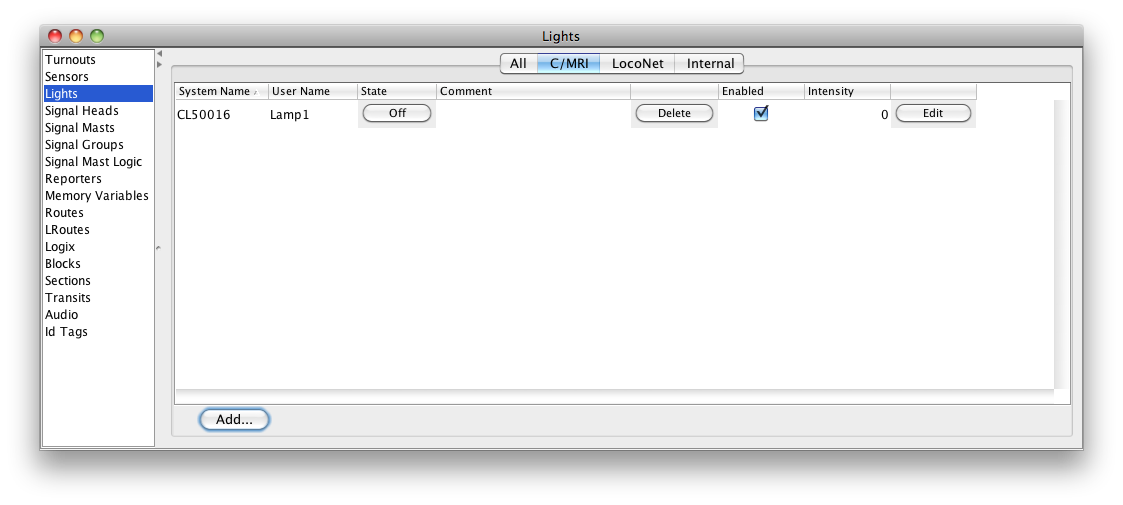
Outputs - Light Table
Similarly, a new Light may be created via the JMRI Light Table When you see a "Light" reference, think "output bit" or "output port". The JMRI Light Table is accessed by selecting Lights in the Tools > Tables menu. All JMRI Lights that have been created are listed in the JMRI Light Table. Turnouts and Lights are different methods of referring to C/MRI outputs from within JMRI. Each method has different setup and control options. JMRI refers to C/MRI output bits as Turnouts or Lights. Lights are on/off switches that JMRI can change to control things on the layout. The JMRI Light Table is accessed by selecting Lights in the Tools > Tables menu. All JMRI Lights that have been created are listed in the JMRI Light Table. Creating a Turnout or a Light to refer to a specific C/MRI output bit, is called "assigning" that output bit. Each Light or Turnout is linked to a specific output line via the address part of the System Name.
Unique Output Bits
A specific output bit may be referred to as a Turnout or a Light, but not both. Each output bit may be assigned only once. When a new C/MRI Turnout or a new C/MRI Light is created, JMRI checks that the specified output bit is available for assignment. If the requested C/MRI output bit is in use by a Turnout or a Light, JMRI will refuse to create the new Turnout or new Light. Note that some C/MRI Turnout control options use two output bits, the addressed one and the next one (see next paragraph), and that both output bits must be unassigned for successful creation of a new Turnout controlled by two output bits.
Forming a JMRI System Name For a C/MRI Bit
C/MRI System Names are formed using the following format: Cpnbbb where C is the default <connection prefix>, p is the <port type>, n is the <node number> and bbb is the <bit number>.
System Names, which represent physical C/MRI hardware inputs or outputs, start with the connection prefix, "C". This assigns the System name to an established CMRInet connection.
The next character in the System Name is the type of physical entity the bit or port is connected. Sensors are designated with a "S", Turnouts with a "T", and Lights with an "L".Next, is the node address as a decimal value, in the range of 0-127. While a node address of zero does not need to be inserted, it is preferred to include it for readability. Also, assigning node addresses greater than 9 makes the System Name more readable.
The last field is the physical bit position in the data stream, and sequentially numbered in the range of 1-999. For example, CS10024 is a C/MRI Sensor, for the 24th input bit on Node 10. CT8001 is the a C/MRI Turnout for the 1st output port on Node 8.
Note: An alternate numbering scheme is available if a node has more than 1000 bits (input or output). See the "Alternate Form For System Names" section. For cross-user compatibility, it is recommended to use the 1-999 style for the numbering scheme.
Alternate Numbering Scheme for C/MRI System Names
An alternate scheme for numbering in C/MRI System Names was developed to give user access to the full number of lines allowed by C/MRI hardware design. The main numbering system allows access to 999 input and output lines on each node. The C/MRI hardware design, however, supports many more bits for USIC and SUSIC nodes. Most JMRI users will never need this alternate scheme, and should use the main numbering scheme.
The alternate numbering scheme is similar to the main numbering scheme, except the node address and bit number are separated by a "B", and both node address and bit number can range to any value supported by C/MRI. The format is: CpnBbbb where C is the <connection prefix>, p is the <port type>, n is the <node number>, "B" is the separator for the node number and the bit number, and bbb is the <bit number>.
For example, CS10B24 is a C/MRI Sensor, for the 24th input bit on Node 10. CT2B1009 is the a C/MRI Turnout for the 1009th output port on Node 2.
Users may use either numbering scheme interchangeably for line numbers up to 999, but must use the alternate numbering scheme for line numbers greater than 999. For ease in communicating with other users, using the main numbering scheme is recommended unless bits greater than 999 need to be addressed.
Creating a Sensor Input
To create a sensor input, open the Sensor table by selecting Tools -> Tables -> Sensors in the main PanelPro menu.
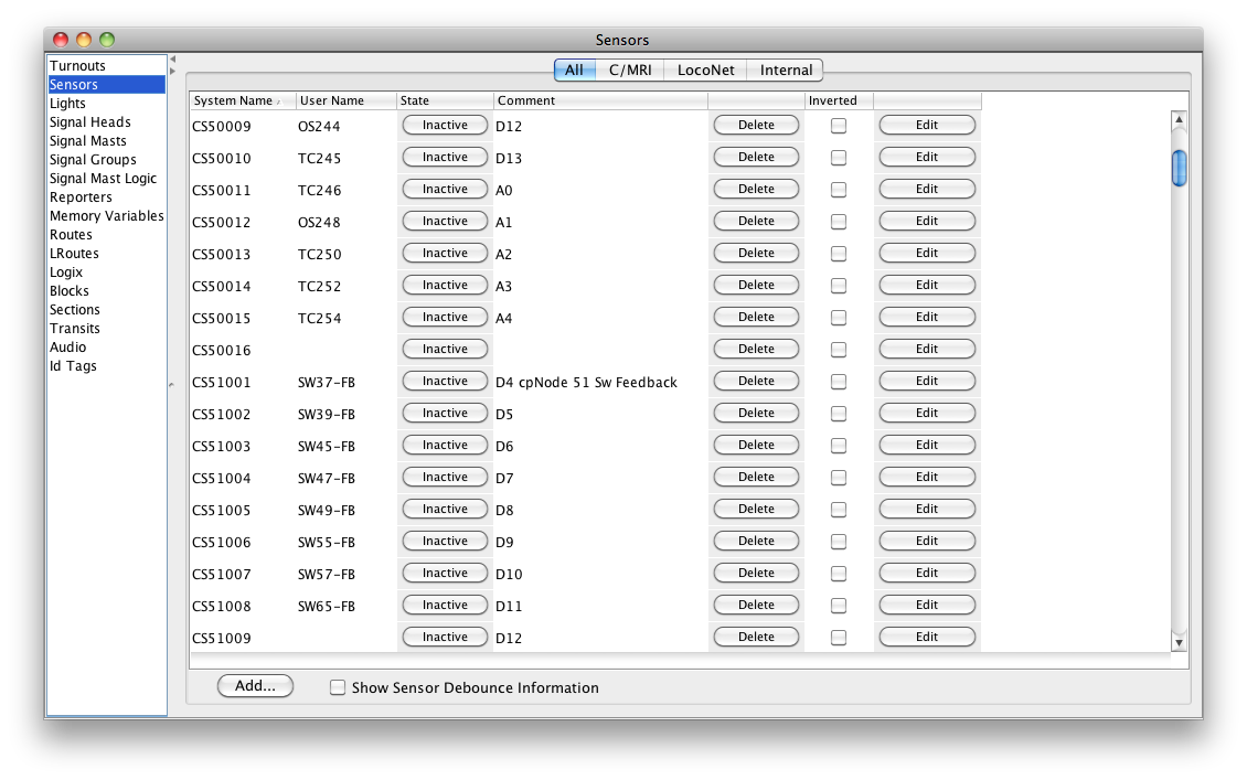
Each C/MRI Sensor is assigned a "System Name". A System Name is the physical data bit or port on the node.
A C/MRI Sensor System Name is in the format: CSnbbb, where: "C" designates a C/MRI system bit, "S" means the bit is a C/MRI Sensor, "n" is the node address, and "bbb" is the address or position of the bit in the input data stream.
A new Sensor may be created via the Sensor Table. Creating a Sensor to refer to a specific C/MRI input bit, is called "assigning" that input bit. Each input bit may be assigned only once, i.e., two different Sensors may not refer to the same C/MRI input bit.
Sensors have two hardware states; Active for On and Inactive for Off. A Sensor is "active" when the input bit is On (grounded) and "inactive" when its input bit is Off.
A sensor can have a User Name assigned, and it is recommended that this be done. A User Name is a descriptive tag, which can be used by other functions and tables within JMRI as the reference to the actual physical bit.
There needs to be one unique sensor defined for every active input bit in the node.
Creating a Turnout Output
To create a turnout output, open the Turnout table by selecting Tools -> Tables -> Turnouts in the main PanelPro menu.
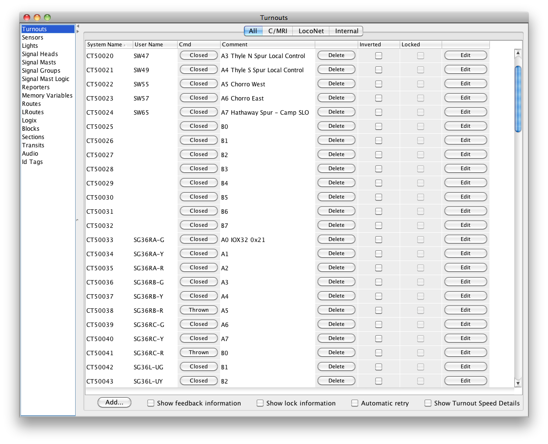
Each C/MRI Turnout is assigned a "System Name". A System Name is the physical data bit or port on the node.
A C/MRI Turnout System Name is in the format: CTnbbb, where: "C" designates a C/MRI system bit, "T" means the bit is a C/MRI turnout, "n" is the node address, and "bbb" is the address or position of the bit in the output data stream.
A new Turnout may be created via the Turnout Table as illustrated below. Creating a Turnout to refer to a specific C/MRI output bit, is called "assigning" that input bit. Each output bit may be assigned only once, i.e., two different Turnouts may not refer to the same C/MRI output bit.
Turnout bits have two hardware states; Thrown for On and Closed for Off. These names are in place for historical reasons. When connected to actual switches, Closed can be "Normal" or the straight route and thrown can be interpreted as "Reverse" or the diverging route.
A turnout can have a User Name assigned, and it is recommended that this be done. A User Name is a descriptive tag, which can be used by other functions and tables within JMRI as the reference to the actual physical bit. This is most useful when assigning output ports which drive signal LEDs or lamps.
When turnout bits are used to control signal LEDs or lamps, one turnout (output) bit would be assigned to the connection wire to the LED or lamp. Multi-color (aspect) signal heads would have one output port assigned to each active color LED. When defining signal heads, the defined turnout name for the color is used to associate the LED control wires. See the example on defining signal heads.
There needs to be one unique turnout defined for every active output bit in the node.
Turnouts and Lights are different methods of referring to C/MRI outputs from within JMRI. Each method has different control options. Always use 'Turnouts' for C/MRI outputs used to control Turnouts (track switches) and for C/MRI outputs used to operate signals.
For historical reasons, C/MRI output bits used to control signal aspects are referred to as 'Turnouts', even if the output bits are used to control Lighted signals. Use 'Lights' to refer to C/MRI output bits used for fascia panel Lights, for Lights in scenery (structure Lighting, street Lights, etc.), and for special purposes where the control options for Lights suit your needs.
Before you can refer to a Turnout or a Light within JMRI, the Turnout or Light must be "created".
A Turnout may be created in a number of ways, including automatically. All JMRI Turnouts that have been created may be viewed in the JMRI Turnout table, accessed by selecting Tools -> Tables -> Turnouts in the main PanelPro menu.
A new Turnout may be created via the Turnout table by clicking "Add" at the bottom of the table. Similarly, a new Light may be created via the JMRI Light Table by clicking "Add" at the bottom of that table. The JMRI Light Table is accessed by selecting Tools > Tables -> Lights Turnouts in the main PanelPro menu. All JMRI Lights that have been created are listed in the JMRI Light Table. Creating a Turnout or a Light to refer to a specific C/MRI output bit is called "assigning" that output bit. Each Light or Turnout is linked to a specific output line via the address part of the System Name.
A specific output bit may be referred to as a Turnout or a Light, but not both. Each output bit may be assigned only once. When a new C/MRI Turnout or a new C/MRI Light is created, JMRI checks that the specified output bit is available for assignment. If the requested C/MRI output bit is in use by a Turnout or a Light, JMRI will refuse to create the new Turnout or new Light. Note that some C/MRI Turnout control options use two output bits, the addressed one and the next one (see next paragraph), and that both output bits must be unassigned for successful creation of a new Turnout controlled by two output bits.
Turnout Control Options
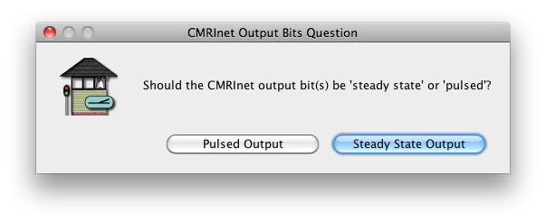
Turnouts (switches) may be controlled using one or two output bits. When a Turnout is created using the Add option in the Turnout Table, the user is asked whether the Turnout is to be controlled using one or two output bits.
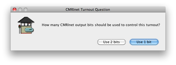
If "Use 1 bit" control is selected, the user must select either 'steady state' or 'pulsed' control.
If 'steady state' is selected, then that output bit is set "Off" for CLOSED ('normal' in C/MRI manuals) or "On" for THROWN ('reverse' in C/MRI manuals). When setting the output bit, JMRI compares the requested state to the state indicated by the current value of the output bit. If these states are different, then the output bit is set as indicated above. If these states are the same, that state is compared to the state indicated by Turnout Feedback. If the states are the same, no action is taken since the Turnout is already in the requested state. If the states are different, the Turnout was probably changed by some means separate from JMRI. To ensure the Turnout is actually set to the requested state, the output bit is first changed to match the state indicated by the Turnout Feedback, then one second later it is changed again to match the requested state. This guarantees a change of state for those Turnout control devices that require a change in state to actually move the Turnout.
If "Use 1 bit" option is used with "Pulsed Output" control, the output bit is "Off" when nothing is happening. When CLOSED or THROWN is requested, this request is compared to the known state of the Turnout (which follows Turnout Feedback). If the known state indicates the Turnout is already in the requested state, nothing is done. If the known state is different from the requested state, then the bit is 'pulsed'. A 'pulse' consists of the bit being turned "On" for one second, then returned to the "Off" position.
If "Use 2 bits" control is selected, the bit referenced in the Turnout system name and the next bit in sequence are used to control the Turnout. For example, if CT33 has two-output-bit control, the 33rd and 34th bits are used to control the Turnout. If two-output-bit control is selected, the user must select either 'steady state' or 'pulsed' control. Steady state control should be selected for stall motor Turnouts, such as a Tortoise, if it is being controlled according to the recommendation in Chubb's C/MRI User's Manual, Version 3.0, page 3-12. With steady state control, for CLOSED, the first bit is set "Off" and the second bit is set "On"; for THROWN, the bits states are reversed, i.e., the first bit is set "On" and the second bit is set "Off".
If "Use 2 bits" control with "Pulse Output" control is requested, both bits are "Off" when nothing is happening. When CLOSED or THROWN is requested, this request is compared to the known state of the Turnout (which follows Turnout Feedback). If the known state indicates the Turnout is already in the requested state, nothing is done. If the known state is different from the requested state, then the first bit is pulsed if CLOSED is requested, or the second bit is pulsed if THROWN is requested. In either case, a 'pulse' consists of the bit being turned "On" for one second, then returned to the "Off" position.
Note that to have two-output-bit control, a Turnout must be created using the "Add" button in the Turnout Table.
Finally, the "inverted" option can be selected. This controls how the C/MRI hardware implements the "On" and "Off" used in the description above. Normally (invert option not selected), "On" refers to a "1" to the hardware; with standard C/MRI hardware, this pulls the output pin down and allows it to sink current. "Off" the corresponds to a "0" to the hardware, turning the output pin off, and causing it to stop sinking current. When "invert" is selected, "On" results in a "0" sent to the hardware, and "Off" results in a "1" being sent. This causes the hardware to act with the opposite polarity.
Creating a Light Output
To create a Lights output, open the Light table by selecting Tools -> Tables -> Lights in the main PanelPro menu.
Each C/MRI Light is assigned a "System Name". A System Name is the physical data bit or port on the node.
A C/MRI Light System Name is in the format: CHnbbb, where: "C" designates a C/MRI system bit, "T" means the bit is a C/MRI turnout, "n" is the node address, and "bbb" is the address or position of the bit in the output data stream.
C/MRI Entry Format Summary
Here's a summary, split up for outputs (eg. Turnouts) and inputs (eg. Sensors):
| In/Out | Entry | Meaning | makes System Name | Mask | Equivalent | Minimum | Maximum |
|---|---|---|---|---|---|---|---|
| i/o | 1003 | Node 1, Input 3 | CS1003 | n digits (node) + 3 digit (pin) | 1:3 | node: 1; pin: 1 | node: 127; pin: 999 |
| o | 3 | Node 0, Output 3 | CT3 | 1 | 999 | ||
| i/o | 4003 | Node 4, Output 3 | CT4003 | n digits (node) + 3 digit (pin) | 4:3 | node: 1; pin: 1 | node: 127; pin: 999 |
| o | 4:3 | Node 4, Output 3 | CT4:3 | 4003 | 0:1 | N/A | |
| i/o | 4B3 | Node 4, Output 3 | CT4B3 | 4003 | 0B1 | 127B999 |
CMRInet Network Management Tools
The C/MRI menu contains three tools which are used to manage nodes in a CMRInet network. Controlling the polling of nodes, displaying the operational states of configured nodes, and monitoring the data message traffic on the network are all functions available in the tool suite.
CMRInet Network Manager
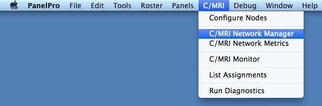
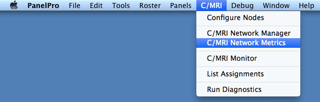
The CMRInet Manager is selected by selecting the C/MRI Network Manager menu item from the C/MRI menu.
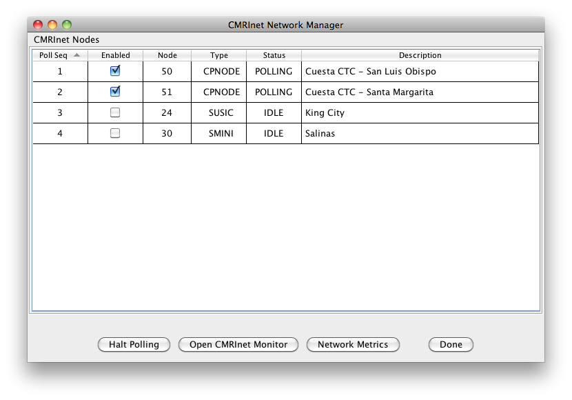
The CMRInet Manager displays the status of each configured node. Polling of individual nodes can be enabled or disabled by checking the Enabled check box for the node. The Status column shows the real time state of the node.
CMRInet Packet Monitor
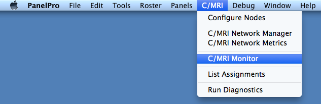
CMRInet protocol messages can be viewed by selecting C/MRI Monitor from the C/MRI menu in main PanelPro window. The monitor window decodes and formats the CMRInet data message to a readable form. The message traffic is displayed in real time with options selected by the user. The window has a scroll bar which will move the display up or down so messages which are off view can be seen.
The data display may scroll by very quickly, depending upon the network line speed. Clicking on the Freeze Display button will stop the display from scrolling. Data messages will still be collected but not displayed until the Resume Display button is clicked. A text message tag can be inserted into the data display (and log file) by typing the text into the field next to the Add Message button. Click on the Add Message button to insert the text into the display.
Data messages can be captured into a text file and saved for later viewing and analysis. Click on Choose Log File. A file create dialog window will open. Select a file name to save the data, then close the window. This action only creates the file for data capture. Click the Start Logging button to start the collection of data. Clicking Stop Logging will stop the data capture and close the log file.
The following screen shows polling with responses for nodes 20 and 21.
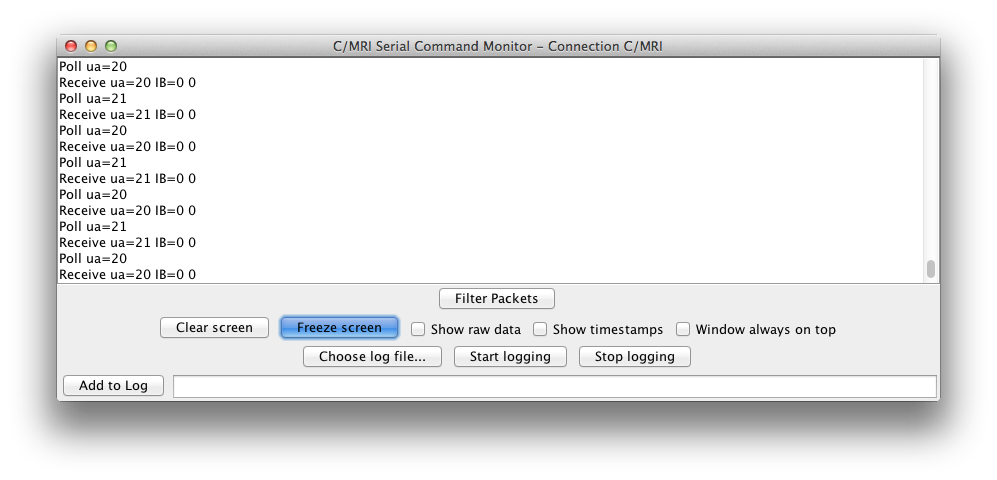
There are display option checkboxes which provide additional information and formatting for the messages.
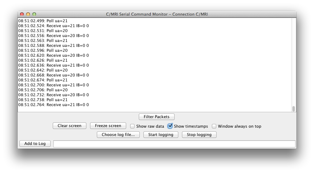
If the Show Timestamps check box option is checked, each message is prefixed with the system time in the form of hh:mm:ss:mss.
The message type (e.g Receive) and node address (ua) are displayed next. The "IB" are the input data bytes. Each byte is displayed as a separate hexadecimal number.
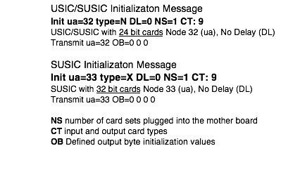
Here are examples of the Initialization messages for each of the node types.
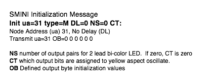
The following screen shows the node initialization message sequence for node 20, followed by the node coming on line and responding to polls. The Init message shows the node address (ua) of 20, followed by the node type (NDP) of C which is a cpNode. DL is the delay value, and Opts are node options entered in the node configuration window. A Transmit message follows with the node address (ua) of 20. OB are the output data bytes as hexadecimal values. Polls are seen followed by the poll/response sequence.
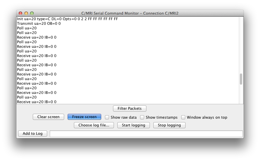
If a node goes off line and stops responding to polls, JMRI will initiate an initialization sequence consisting of five polls. If five polls result in no responses (timeouts) the Init/Transmit message sequence will be done. This poll/init/transmit message sequence is repeated until the node comes back on line.
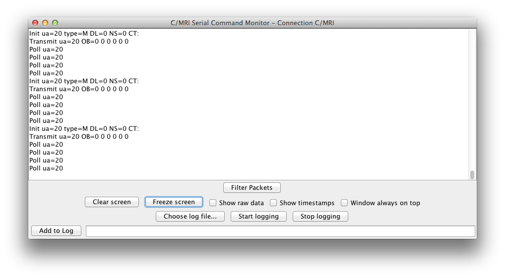
The following screen shows a poll to node 20, followed by a response, then output bytes sent to the node.
![]()
The following screen shows all of the display options enabled. The order of options is:
timestamps as hh:mm:ss:mss, raw data in hexadecimal, data message
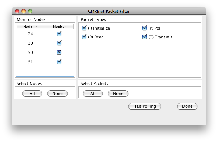
CMRInet messages can be filtered from display by clicking the Filter Packets button. The packet filter window lets you select the nodes and message type to display in the monitor window. The Select Nodes, Select Packets buttons allow for quick select or de-select of the filters. Clicking the Halt Poll button will stop network polling. Clicking Resume Polling will restart polling.
CMRInet Network Metrics
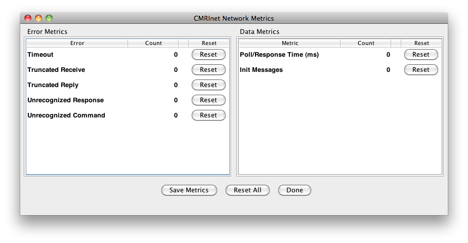
Anytime the CMRInet is active, a network metrics collector is running in the background. The metrics collected are errors and performance or instrumentation data. CMRInet metrics can be viewed by selecting C/MRI Network Metrics from the C/MRI menu in main PanelPro window
Each of the Error and Data Metric values can be reset to zero by clicking the appropriate Reset button. All of the metrics can be reset to zero by clicking the Reset All button. Metric data can be saved to a text file by clicking on the Save Metrics button. A file create dialog window will open, enter a file name for the metric data. <PHOTO-CMRInet Metrics>
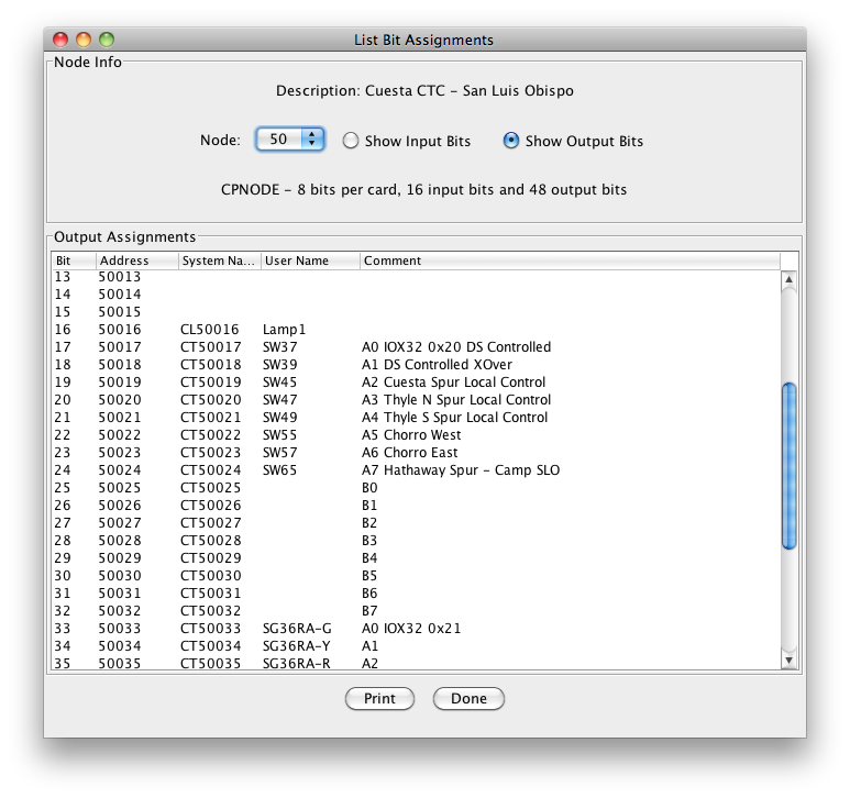
Listing C/MRI Bit Assignments
For each node, you can view a summary list of C/MRI bits that are in use and those that are available.
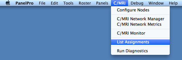
Select List Assignments in the C/MRI main menu or from the Select column in the Node Configuration Manager to bring up Bit Assignments window.
List Assignments is useful for checking that you have configured the correct numbers of input and output bits and the correct node address for each node. The Assignment Table contains a line for each configured input or output bit. Each line also contains an address column showing what address to use for that bit in JMRI's C/MRI system names. Printing blank assignment lists for each node provides a convenient paper form for use in setting up your input/output bit assignments. The Comment field information is also displayed.
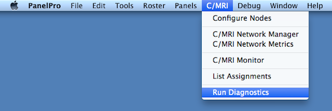
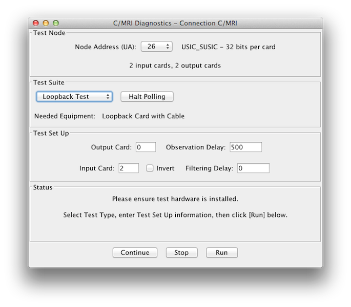
Diagnostics
Diagnostics are useful for checking the functioning of your C/MRI hardware. These automated procedures are controlled via a dialog available by selecting Run Diagnostics in the C/MRI menu. Some of the diagnostic tests require external hardware to operate. Chapter 6 of Bruce Chubb's C/MRI User's Manual, Version 3.0, describes a test output card and loopback cable. These items connect to input and output ports on Classic nodes and provide hardware devices which are driven by the diagnostic test code. An integrated test card (IOTEST) from MRCS provides compatible test hardware support.
By opening the C/MRI Monitor, the test message traffic can be viewed.
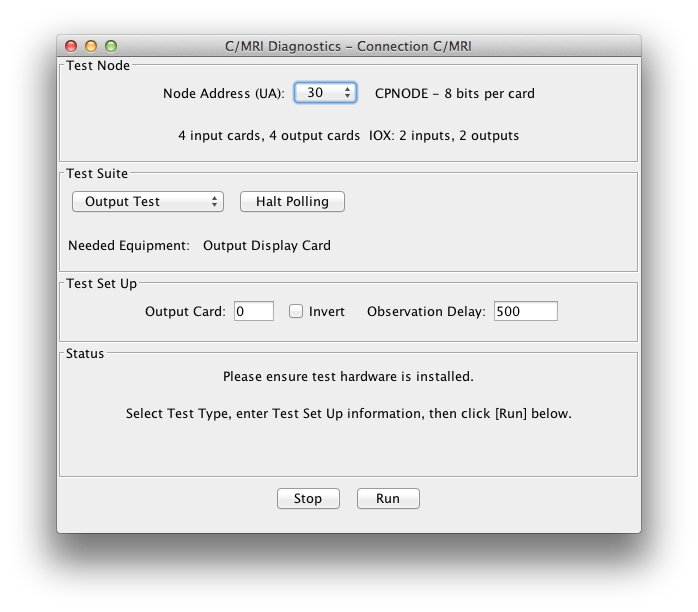
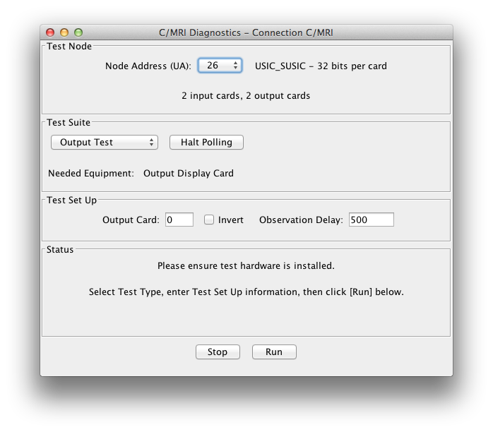
The C/MRI Diagnostics window has five sections.
Test Node provides a popup menu for the selection of the node to be tested. The menu only displays the addresses of configured nodes for the connection. Node type and card assignment information for the selected node are displayed.
Test Suite has the test selection popup menu which lists available tests. The suggested equipment needed to run the test is also listed. The Halt polling button stops polling of nodes on the connection. Polling should be halted when running diagnostics so as not to interfere with the test sequences.
Test Set Up provides user input fields for data card selection and options for each test suite.
Status displays the progress of the running tests and any error messages related to the test sequences.
Test Control buttons displayed at the bottom of the window control the various test sequences and are specific to each test suite.
Output Test
The Output Test writes a walking bit pattern to the output test card, lighting the LEDs corresponding to the bit pattern. The number of bits written is based upon card size (8, 24, 32). The Output Card number is checked to be a valid defined output card. Observation delay is the number of milliseconds delay between each write. Checking the Invert box flips the state of the bits. This is useful for output cards which drive Common Anode (sinking) devices.
Loopback Test
The Loopback Test uses a loopback cable connected to a card of outputs and a card of inputs. The test writes a data value pattern to each output port and reads the value from the corresponding input port. The input value is compared to the output value and displays any comparison errors. If a compare error occurs, the test is paused. Clicking the Continue button will write the next value to the output. Observation Delay and Filtering Delay adds time delay intervals to the write and read operations. Invert works the same as in the Output Test.
Send Commands
Send Commands provides raw CMRInet packet transmissions to the test node.
Initialize Node transmits an Initialize (I) message to the node. The node would then execute the onboard initialize code.
Poll Node transmits a poll message (P) to the node. The count of input bytes in the response is returned. If the node does not respond to the poll, a timeout error is reported.
Write Bytes transmits (T) the user entered byte string to the output card number. The bytes need to be entered as hexadecimal values separated by a space. The maximum number of bytes written is the defined by size of the card (1, 3, 4). Invert works the same as in the Output Test.

CMRInet Network Connections
Using USB-serial adapters
Most C/MRI systems use RS-422/485 electrical signals to communicate between the nodes and the computer. There are several ways to generate them:
1. If your computer has a built-in serial port (RS-232 connection), you can use an RS-232 to RS-422/485 convertor. There's one you can build as part of the C/MRI system, or you can buy a commercial one.
2. If your computer has a USB port, you can buy a commercial USB to RS-422/485 adapter and use that.
3. If your computer has a USB port and you have a RS232 to RS-422/485 convertor, you can install a USB-to-RS232 adapter (sometimes called a "USB-to-serial converter"), then connect the RS232 output of that to the RS232 input of the RS232 to RS-422/485 convertor.
Note that if you're using the Chubb RS232-to-RS-422/485 converter, some USB-to-RS232 adapters will require that you connect certain RS232 control leads that are not handled by the Chubb interface board:
o DSR - DTR (pins 4 & 6 on the DB9 connector)o RTS - CTS (pins 7 & 8 on the DB9 connector)
In all cases, the communications line will end up appearing as a serial port on your computer. In Windows, this is a COM port, in other computers it's a named serial device. You will need to select the proper one when configuring JMRI. If no serial devices appear in the selection popup menu, you may not have any operating system serial device drivers installed.
Using An Ethernet Network Connection
JMRI allows you to connect to C/MRI nodes through a network connection. JMRI communicates via the TCP/IP protocol across a network to a network-to-serial adapter, which converts the network connection to a serial stream that then goes through a RS-422/485 convertor to the C/MRI node(s).
The network-to-serial adapter is sometimes called a "terminal server". It's also sometimes called a "Lantronix box" after an early manufacturer of these, though they're now available from multiple sources. The adapter has to be configured with the correct serial parameters for your C/MRI system, including the proper baud rate and 8-data-bits, no parity. You will probably need a RS232-to-RS-422/485 adapter on the output of the network adapter.
Some hobbyists have also built C/MRI nodes that have native Ethernet connections. JMRI communicates with them via a direct TCP/IP connection using the C/MRI protocol, but in this case there's no need for a RS-422/485 convertor.
To configure JMRI to use a network connection, go to the Preferences screen, Connections tab. After selecting C/MRI for the System Manufacturer, select "Network Interface" for the System Connection. Then enter the IP address (or node name, if it has one) of your network-to-serial adapter in the IP Address / Host Name field. If it uses a non-standard port number, check the Additional Configuration Settings box and enter the port number. Click Save and restart the program.
Running JMRI when disconnected from your C/MRI system
JMRI continually polls the C/MRI hardware for status changes. If one or more C/MRI nodes are not responding, eventually their inputs (Sensors) are set to the UNKNOWN state to indicate that JMRI has lost contact with those devices on the layout.
Although this is the right thing to do when you're really connected to the hardware and trying to operate the layout, it can get in the way if you're running JMRI without your layout connection. You might want to do this, for example, to work on your panels while away from the layout, or while the layout needs to be powered off for some reason.
To accommodate using JMRI without an active layout connection, in the JMRI 2.3.2 release a "C/MRI Simulator" connection was made available in the Preferences.
Please note that this is only meant for users who already have a working C/MRI connection already configured. Please do not try to use the C/MRI simulator before configuring a valid connection to C/MRI hardware, as it will not work.
Once you have your C/MRI connection configured, when your hardware is not available you can just go to the JMRI Preferences, select "C/MRI Simulator", save Preferences, quit and restart. Don't change any other settings!
When the C/MRI hardware is again available, go the JMRI Preferences, select "C/MRI Serial", save Preferences, quit and restart.
PanelPro Signaling Example Using C/MRI
The following is an example of what is needed to create a simple ABS signaling system using an SMINI node and Control Panel Editor (CPE) in PanelPro. The SMINI will be set to node address 15.
The focus of the example is to show the relationship between the input and output ports (bits) on the SMINI and the logical connection to the various JMRI device tables. Only the device table information will be defined. The required Logix and Conditionals will not be described.
The section to be signaled is a classic mainline/passing siding triad. The operating scheme is assumed to be Automatic Block System (ABS), with the trains given written authority to occupy the track segments and operate the switches if needed. Block occupancy and turnout position determine signal aspects. All Stop aspects are Absolute.
Signals, which control the entrance and exit to the siding, will display only Yellow (Approach) and Red (Stop) as it is assumed these are low speed routes.
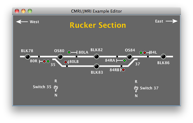
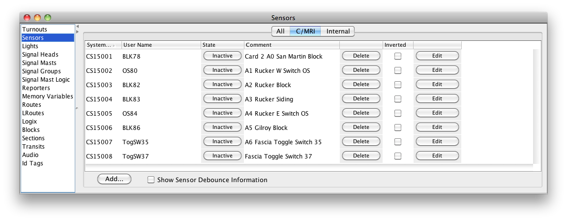
Sensors are the block occupancy detectors and two fascia toggle switches controlling the turnouts. The detectors will present an Active state when a block is occupied, and Inactive when a block is vacant. The switch controls, will present Inactive for the turnout in Normal, and Active if the turnout is Reverse.
Inputs are assigned to Card 2, ports A0 through B0. The output of block detector BLK78 is connected to SMINI Node 15, Sensor input, Card 2, port A0. The comment field is used to document the physical SMINI port and a description of the track section.
By referring to the port names printed on the SMINI circuit board, the connection is path is fully defined. User Names are used when writing Logix statements. A consistent naming scheme should be adopted for creating easy references in the Logix Conditionals. One should be able to look at a User Name and immediately identify what type of device is connected to the port.
The Sensor table is a live view of the state of the port. For Sensors, applying a signal ground to the port will cause the State to change from Inactive to Active. This technique is a great way to verify if the node is communicating with the Master and that the port assignments match the actual connected device.
Outputs are defined in the Turnout table. As described earlier, the name "turnout" is historical. Again, just think of turnouts as the output ports. Output states are Closed for Off, and Thrown for On. If the port is connected to an actual turnout, Closed would normally be "Normal" and Thrown would be "Reverse". The "Cmd" column displays the live state of the port. Clicking on the Cmd button will toggle the turnout from Closed to Thrown. This capability can be used to test connections and proper operation of output devices.
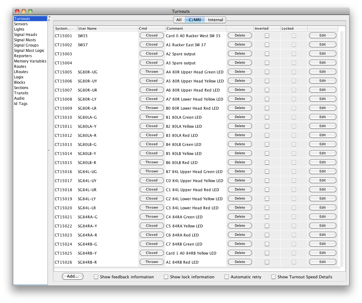
There are two output ports assigned to turnout controller bits. The turnout control bits are assigned to Card 0, ports A0 through C7, and Card 1 port A0. The turnout motor control bit for SW35 is connected to SMINI Node 15, Turnout output, Card 0, port A0.
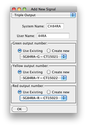
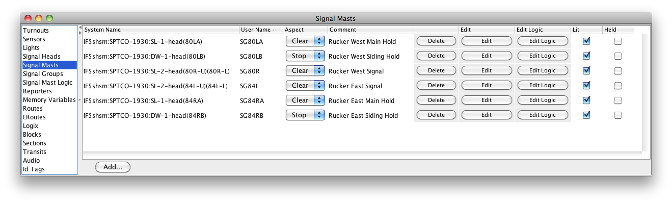
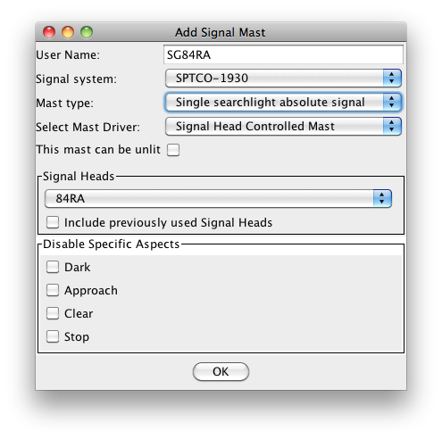
Six signal masts are required for signaling. Two are dual head with an upper and lower head. LED's are assumed to be the lamps used for aspect illumination. One output bit is required for each color. All LED commons are tied together. Signal mast 80LA is a single head signal.
There are three LEDs in the head; Green, Yellow, and Red. Each wire attached to a color LED must be connected to an output port. The green LED for signal 80LA (SG80LA-G) is connected to SMINI node 15, turnout, bit 10, Card 0, port B1.
JMRI Help
Third Party info
Supported Hardware
- Chubb C/MRI USIC
- Chubb C/MRI SMINI
- Chubb C/MRI SUSIC
- Model Railroad Control Systems (MRCS) CPNODE
For more information on C/MRI (including the C/MRI User Manual), please see:
- JLC Enterprises web site
- SLIQ Electronics
- C/MRI Users Yahoo group
- Model Railroad Control Systems (MRCS)
Thanks and congratulations to all who contributed!
Copyright © 1997 - 2018 JMRI Community.
JMRI®, DecoderPro®, PanelPro™, SignalPro™, TrainPro™, DispatcherPro™, OperationsPro™ and associated logos are our trademarks.
Additional information on copyright, trademarks and licenses is linked here.
Contact us via the JMRI users Groups.io group.
Site hosted by:
![]()
See also the site status page.