Adding & Editing Signal Heads
JMRI needs to know how a Signal Head on the layout is connected to the electrical hardware. Once JMRI knows that, it can send the right DCC commands to control the Appearance of a Signal Head.
The "Edit Signal Head" panel provides for viewing and changing optional information for existing Signal Heads. Use the "Edit" button in the Signal Head Table to open a dialog for that Signal Head. Only one Signal Head may be edited at a time. Signal Type and Signal System may not be changed once they have been created. After making changes in the dialog, click the "Update" button at the bottom of the panel to change Signal Head information. Click "Cancel" to exit without making any changes. Closing the Edit Signal Head panel is equivalent to clicking "Cancel".
The "Add New Signal" dialog that is opened by clicking on the "Add..." button at the bottom of the Signal Head Table lets you choose a Signal Head Connection type from the following list.
Available Signal Head Connection Types
- Virtual
- This type doesn't connect to the layout at all. Use it when you want to e.g. display a signal on a panel, but don't have a real one on the layout.
-
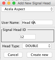 Acela
Acela -
This type controls signal heads attached to a CTI Electronics
Acela
SignalMan module.
In the text field, enter a System Name for an Acela signal head, e.g. AH01. For more information on Acela hardware, see the Acela hardware help page.
- DCC Signal Decoder
-
This type controls Signal Heads attached to a decoder
that uses the DCC signal packets defined by the NMRA DCC
Working Group for control. (You might be able to find
information on those DCC packets on page 9 at
this link; the NMRA web site is difficult to link
into, so if that doesn't work, search for "NMRA 9.2.1
Extended Accessory Decoder Control Packet Format"). This
is a special protocol defined for driving Signal Heads,
and is different from how "accessory decoders" (e.g.
Turnout outputs) are controlled.
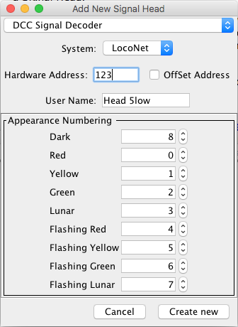
Enter the DCC address as a number. The Offset Address check box uses an alternative interpretation of the addressing scheme that might be in use.
Each possible Appearance of the Signal Head is assigned a different number; from here you can assign different numbers for each Aspect to suit the hardware being used.
The Team Digital SHD2 Signal Decoder is a Signal Head decoder using a different address for each Signal Head. A Signal Mast attached to the SHD2 must be configured as one or more Signal Head controlled masts using the DCC Signal connection type. Instructions can be found on the Team Digital website under the Applications > SHD2 menu.
Note: The Signalist SC1 can also be configured as individual Signal Heads (searchlight with bicolor, tricolor or RGB LEDs or multi-lamp with individual LEDs), but is much easier to use when configured as a complete Signal Mast with all Signal Heads on a single DCC address using the DCC Signal Mast driver. In that case you don't need to add Signal Heads for your signal. Key difference between a Signal Head and a Signal Mast is the number of different states each might have. A Signal Head only has (up to) 8 Appearance entries, but a Signal Mast can have up to 32 (0-31) possible states, called Aspects in that case. The command going out is the same but the number of possible values differs. 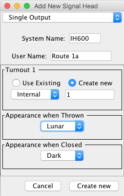
- Single Output
-
This connection type controls a Signal Head with one
output. A Signal Head connection that uses just one
output line to indicate up to 2 Appearances plus
Flashing. You can select 2 Appearances from the following
list: Dark, Red, Yellow, Green and Lunar. The output
coding is such that a Turnout status Thrown (On)
controls one Appearance and Closed (Off)
controls the other. Flashing allows for a third
appearance, which will flash between the two Appearances
configured. The connection can be to a single lamp/LED to
display a single appearance. An alternative method is to
connect a pair of LEDs to the single output wired up so
that when the output of the decoder is On you get one
color and while the output is Off you get the other. This
type could also be used to control mechanically operated
Signals that only have two Appearances and therefore
always have an Appearance. It is possible to gain a third
"Flashing" Appearance. If you have Dark and a color
selected, then the end result is an additional Flash
color option. If two colors have been selected, you are
given a Flash option for both colors but this will result
in the colors flashing alternatively. These connections
are controlled via the JMRI Turnout logic, and therefore
appear in the Turnout Table. They're not connected to
switch motors, though, they're just electrical outputs.
For each connection, enter the appropriate JMRI Turnout for the electrical connection on the layout, either from the drop down list of already-defined Turnouts or by creating a new Turnout for a particular connection.
Select one of the listed Appearances for both:
Appearance when Thrown - The appearance displayed when the connection is in the Thrown State.
Appearance when Closed - The appearance displayed when the connection is in the Closed State. 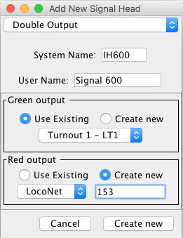
- Double Output
-
This type controls a Signal Head via two electrical
connections. One goes to a green lamp/LED, and the other
to a red one. Yellow is created by turning them both on
at the same time.
For each connection, enter the appropriate JMRI turnout for the electrical connection on the layout, either from the drop down list of already-defined turnouts or by creating a new turnout for a particular connection. They need not be consecutive or in any particular order.
- Double Output Head
- A Signal Head connection that uses just two output
lines to indicate 4 signal Aspects.
Usually these Aspects will be Clear, Approach, Stop, and Dark. The output coding is such that one turnout Thrown (On) controls the Stop and the other Thrown (On) controls the Clear. Both outputs Thrown (On) controls the Approach, and both Closed (Off) is Dark. Each aspect change requires that two turnout commands be sent. - Triple Output
-
This type controls a Signal Head via three electrical
connections. One goes to a green lamp/LED, one to a
yellow lamp, and the third to a red one.
These connections are controlled via the JMRI Turnout logic, and therefore appear in the Turnout Table. They're not really connected to switch motors, though, they're just electrical outputs.For each connection, enter the appropriate JMRI turnout for the electrical connection on the layout, either from the drop down list of already-defined turnouts or by creating a new turnout for a particular connection. They need not be consecutive or in any particular order.
If you need to debug one of these Signal Heads, start by checking whether the Turnout connections work. - Triple Output RGB
-
This type controls a Signal Head via three outputs to
indicate 5 signal Aspects. Usually these aspects will be
Clear, Approach, Stop, Restricting and Dark.
The output coding is such that one Turnout Thrown (On) controls the Stop and another Thrown (On) controls the Clear. Both of these outputs Thrown (On) controls the Approach, all three On controls the Restricting, and all three Closed (Off) makes for Dark. Each Aspect change requires that three commands be sent.
The first connection drives a green lamp/LED, the second a red one, and the third to a blue one. They are controlled via the JMRI Turnout logic, and therefore appear in the Turnout Table. They're not connected to switch motors, though, they're just electrical outputs.For each connection, enter the appropriate JMRI Turnout for the electrical connection on the layout, either from the drop down list of already-defined Turnouts or by creating a new Turnout for a particular connection. They need not be consecutive or in any particular order.
- Quad (quadruple) Output
-
This type controls a Signal Head via four electrical
connections. One goes to a green lamp/LED, one to a
yellow lamp, one to a red lamp, and the fourth to a
"lunar" (white) one.
These connections are controlled via the JMRI Turnout logic, and therefore appear in the Turnout Table. They're not really connected to switch motors, though, they're just electrical outputs.For each connection, enter the appropriate JMRI Turnout address for the electrical connection on the layout, either from the drop down list of already-defined turnouts or by creating a new turnout for a particular connection. They need not be consecutive or in any particular order.
- SE8C 4 Aspect
-
The output is controlled by a single turnout command per
Aspect change. One turnout command changes between "Stop"
and "Clear", and the second turnout command changes
between "Approach" and "Dark".
This type controls Signal Heads attached to a Digitrax SE8C signal driver card.
Because each SE8C 4 Aspect Signal Head works with a specific DCC address, its System Name is determined automatically from that address; you don't have to enter it. For example, the SE8C 4 Aspect Signal Head for hardware address 257 will be given a system name based on that. See page 5 through 7 of the Digitrax SE8C Manual.
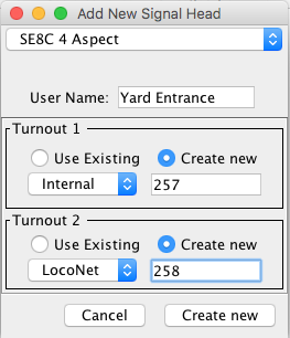 You can optionally enter a more readable
User Name if you'd like.
You can optionally enter a more readable
User Name if you'd like.In the "Turnout number" box, enter the appropriate DCC address of the SE8C output as a number. For example, the 1st signal head on the 1st SE8C, as configured from the Digitrax factory, is "257". Select "Create new", then select your layout connection (usually "LocoNet") in the drop down box, and enter "257" in the field next to it. Do the same in the second Turnout field, entering "258" as the second Signal Head address.
For more advanced usages, for example if you're using more than one type of layout hardware, you can either select a Turnout from the drop down list of already-defined Turnouts or by creating a new Turnout for a particular connection.
- LDT LS-DEC
-
This type is particularly useful for European signaling.
It controls Signal Heads attached to a Littfinski
DatenTechnik (LDT) LS-DEC
signal decoder, or a Marathon Model DP2N
decoder.
These controllers use seven DCC Turnout (accessory decoder) addresses to specify the seven possible Appearances of the Signal Head. Enter those, either from the drop down list of already-defined Turnouts or by creating a new turnout for a particular connection. They need not be consecutive or in any particular order.
For more information on configuring these signals, see the LDT Examples page. 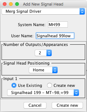
- MERG Signal Driver
-
This driver type controls a Signal that uses a MERG
Signal Driver (SD2). An SD2 is connected to DCC using a
steady state accessory decoder. The number of Aspects to
be displayed on the Signal Mast, will determine the
number of Turnout
outputs required, ie.
2 Aspects: require 1 Turnout (pictured at right)
3 Aspects: require 2 Turnouts
4 Aspects: require 3 TurnoutsThe MERG Signal driver in JMRI has been set up to control the SD2 Aspect output only. It does not control the other features of the SD2 such as "Steam Rules" or "Feather", however these can easily be configured using Logix or Routes.
Notes - The MERG SD2 driver does not support a Flashing yellow Aspect. For Flashing yellow Aspects an additional circuit is required as documented in the MERG Technical Bulletins.
As the MERG SD2 driver goes beyond the Green/Yellow/Red Aspects supported in JMRI with a Double yellow (yellow over yellow) aspect, the Double yellow state is represented in the status as a "Lunar".
Further information on the Merg Signal Driver can be found at MERG - Grapevine
- This type controls Signal Heads attached to a ProTrak Grapevine node.
In the text field, enter a System Name for a Grapevine Signal Head, e.g. GH1204 for the 4th connector on the 2nd bank connector of the 1st node. For more information on how those names are generated, see the page on Grapevine names.
Notes
- If you need to debug one of these Signal Heads, start by checking whether the (Turnout) connections work. You can do this by going to the Turnout Table and changing the output setting there. Setting e.g. the Turnout on the "Green" connection to Thrown should light the green lamp.
Back to the Signal Head Table help page.
Thanks and congratulations to all who contributed!
Copyright © 1997 - 2018 JMRI Community.
JMRI®, DecoderPro®, PanelPro™, SignalPro™, TrainPro™, DispatcherPro™, OperationsPro™ and associated logos are our trademarks.
Additional information on copyright, trademarks and licenses is linked here.
Contact us via the JMRI users Groups.io group.
Site hosted by:
![]()
See also the site status page.