The Layout Editor
Contents
This document describes Layout Editor and how to use Layout Editor to make PanelPro panels. The document is divided into sections; click below to jump to the named section. The minimum reading to get started is Introduction to Layout Editor Panels and Getting Started with Layout Editor. Then you may want to jump to Putting Finishing Touches on your Panel to see more of what's possible before reading the various other sections in detail.
Notice: The signal related portions of this help file have not been updated and apply mainly to signal heads. Those discussions predate signal masts. since 2.14 Masts are fully supported in Layout Editor Panels, but only described briefly.
- Introduction to Layout Editor Panels
- Getting Started with Layout Editor
- Using the Layout Editor Tool Bar
- Using the Layout Editor Floating Tool Box
- Using a Panel's File Menu
- Using Layout Editor's Options Menu
- Using Layout Editor's Tools Menu
- Using Layout Editor's Zoom Menu
- Using Layout Editor's Marker Menu
- Editing and Removing Items
- Turnouts
- Track Segments and Connection Points
- Level Crossings
- Turntables
- Backgrounds
- Blocks
- Track Drawing Options
- Blocks, Memory Labels, and Train Tracking
- Tips
- Putting Finishing Touches on your Panel
Introduction to Layout Editor Panels
JMRI supports multiple panels, either Layout Editor type or Panel Editor type. All panels that have been created or loaded are listed in the submenu of Show Panel in the Panels menu. You can minimize or close a panel window, and bring it back as the front most window by selecting it in this submenu. Multiple monitors are supported to the extent that the operating system allows, and a single panel may be stretched to occupy more than one monitor.
To save your Layout Editor panel, select Save Panels... in the File menu of your Layout Editor panel, or in the Panels menu. When you do this, all panels listed in the submenu of Show Panel are saved, along with all shared configuration items (sensors, turnouts, signal heads, etc.). To make it easier to save your panel often, Layout Editor provides the menu item, Save Location and Size, in the Options menu. Once you have sized and positioned your panel exactly as you would like it to come up when loaded, select this item and save your panel. You need not be concerned about the position and size of your panel changing during subsequent saves! The position and size of your panel will only change when you select Save Location and Size. So save your panel often to preserve your work.
Layout Editor supports the construction and display of PanelPro panels. Layout Editor is similar to the traditional PanelPro Panel Editor, except it supports a drawn track diagram instead of an icon-based track diagram. Because of the way it works, Layout Editor captures the full connectivity of your layout as you draw it. Several automated tools are available to make setting up your panel easier.
Layout Editor is implemented using a tool bar at the top (default location) of your panel. This tool bar may be switched on and off using the Edit Mode item in your panel's Options menu. When you create a new Layout Editor panel, your new panel appears with the Edit Mode tool bar displayed at the top of your panel, and with a system-specific help bar displayed at the bottom of the panel. The help bar describes how to use the Layout Editor user interface. The help bar probably should be turned off (using the Options menu) once you are familiar with the user interface.
Layout Editor supports several options that you may or may not elect to use when you draw your track diagram. Sections of track may be designated as mainline track to differentiate it from side track (the default). Mainline track and side track may be drawn with different width lines. You may divide your layout into blocks, with each block having an occupancy sensor and each drawn with different track colors for occupied and unoccupied states, allowing the track in a block to change color as a train enters and leaves that block. Normally track segments are drawn as solid lines, but you can designate chosen segments as dashed to show tunnels or tracks crossing at different grades. You can also designate a track segment as hidden so it is displayed only when the tool bar is shown. These options may be set up as you draw your panel, or you may add them later.
Below is a short tutorial on the basics of using Layout Editor. A more complete tutorial is available for download as a pdf file on the JMRI web site. See Using the JMRI/PanelPro Layout Editor and its two associated demonstration .xml files.
Getting Started with Layout Editor
To get familiar with the Layout Editor user interface, try the following:
1. Select New panel..., then Layout Editor in the Panels menu. You should see a blank panel window with a tool bar at the top, and a help bar at the bottom.
2. Move the cursor around inside the blank panel. Note that as you move, coordinates are displayed at the upper left of the tool bar--x (horizontal) and y (vertical). (This is to aid in aligning items as you draw them.) Move the cursor over the radio buttons, check boxes and entry fields in the tool bar, noting that each has a tool tip.
3. To add a right-handed turnout, first, select RH for Turnout Type in the top row of the tool bar. Then, while depressing the shift key, click the mouse (left click on a two-button mouse) on a point about one third down and one third across from the upper left of your panel. A right-handed turnout should appear. The three red squares at the ends of the throat and the continuing and diverging legs of the turnout are connection points for Track Segments. The round circle at the center of the turnout is where you should point to get the turnout's popup menu.
4. To add a left-handed turnout, first, select LH for turnout type. (Note that the selection is automatically turned off at RH.) Type "180" in the Rotation box at the upper right of the tool bar, to rotate the new turnout. While pressing the shift key, click the mouse on a point at the same height as the other turnout, but to the right about two or three inches. A left-handed turnout should appear with its throat facing away from the right-handed turnout.
5. To add track segments to connect the two turnouts, select Track Segment on the second row of the tool bar. While holding the shift key down the whole time, depress the mouse button on the diverging connection point of one turnout, and drag to the diverging connection point of the other turnout, and release the mouse button when the cursor changes shape. You should see a track segment connecting the two turnouts, and both connection points should change color to green, indicating they are full, that is they have the maximum number of connections allowed. Similarly press and drag with shift pressed to add a track segment connecting the continuing legs of the two turnouts. You've drawn a passing siding.
6. To add a turnout for an industry siding, select LH for a left-handed turnout, and enter 0 in Rotation. Then with shift pressed, click on a point a couple of inches below and slightly to the right of the turnout on your left.
7. To connect this turnout with the upper passing track and form a simple oval track diagram, select Anchor Point on the third row of the tool bar. An Anchor Point is a node in a track diagram that can accept two connecting track segments; it's used to place connected track segments so that they look reasonably nice (and also to divide blocks). While holding shift down, click on a point exactly to the left of the turnout on your upper left, and again on a point directly below this one, but exactly to the left of the lower turnout. Next click on a point about 1/2 inch to the left and 1/2 inch below the upper anchor point, and again on a point 1/2 inch to the left and 1/2 inch above the lower anchor point. You should now have four anchor points outlining the left side of the oval. Connect these four points and the turnout throat connection points with track segments--select Track Segment, then with shift pressed, click and drag to create each of the five track segments needed. Note that the anchor point rectangle will change from red to green when it has two connections. Similarly repeat this procedure to draw the right side of the oval.
8. Turnout positions and anchor point positions may be adjusted to make the track diagram look nice by holding down the meta key (check the help bar to see which key is the meta key), and dragging each anchor point or turnout. To adjust the position of a turnout, drag the center point of the turnout with the meta key pressed.
9. Next complete the industry siding. The diverging connection point of the lower turnout should be the only box needing a connection (colored red). Select End Bumper in the tool bar. An End Bumper is a node in a track diagram that can accept only one connection. With shift pressed, click on a point exactly to the right of the diverging connection point of the lower turnout. Connect your end bumper to the diverging connection point by holding shift down, while pressing the mouse button on the diverging connection point and dragging to the end bumper. Your track diagram should look like the following:
10. Select Edit Mode in the Options menu to hide the tool bar (and the help bar) and see how your track diagram of a simple oval layout would look in a final panel. You should see connection points and edit circles disappear. Also note that, when not in Edit Mode, items may not be repositioned and popup menus are not active.
The above steps demonstrated the basic steps needed to draw a track diagram. You can clear this demonstration panel by selecting Delete this panel... in the panel's File menu, and begin to construct a track diagram of your layout. Read the items below to learn more about how to add content to track diagram items and how to add icon items to your panel.
Note: Layout Editor tools for placing signal heads and automatically configuring signal logic require that turnouts and block boundaries (see below) be oriented vertically or horizontally on your panel. To make maximum use of these tools, design your panel with turnouts oriented vertically or horizontally (the orientation does not have to be exact, just mostly vertical or mostly horizontal).
Using the Layout Editor Tool Bar
The tool bar is used to add items to a panel, and to provide information for the items added. The item to be added is selected using one of the following radio buttons in the tool bar:
- RH - selects a right-handed turnout
- LH - selects a left-handed turnout
- WYE - selects a wye turnout
- Double X-over - selects a double crossover turnout
- RH X-over - selects a right-handed single crossover turnout
- LH X-over - selects a left-handed single crossover turnout
- Single Slip - selects a single slip turnout
- Double Slip - selects a double slip turnout
- Level Crossing - selects a level crossing track (a diamond)
- Track Segment - selects a piece of connecting track
- End Bumper - selects a connection point at the end of a track
- Anchor Point - selects a connection point between two track segments
- Edge Connector - selects a connection point between two track segments on different panels
- Text Label - selects a label showing the content of the entry field
- Memory - selects a label showing the contents of the memory whose name is entered on the right
- Block Contents - selects a label showing the contents of the block whose name is entered
- Multi-sensor - selects a multi-sensor--A dialog is displayed allowing the multi-sensor to be defined. Before creating the multi-sensor, a name must be entered for every sensor to define the multi-sensor completely.
- Sensor Icon - selects a sensor icon showing the sensor whose name is entered on the right.
- Signal Icon - selects a signal head icon showing the signal head whose name is entered on the right
- Signal Mast Icon - selects a signal mast icon showing the signal mast whose name is entered on the right
- Icon Label - selects a general purpose icon
The top 13 items are used to create a track diagram, and are new with Layout Editor. The remaining eight items are icon-based and are similar to corresponding icon items in Panel Editor.
To add all items except Track Segment:
- Select its check box (check boxes of the other items will automatically be deselected).
- Enter any other information needed (see below).
- Move the mouse cursor to the point on the panel where you would like the item to appear.
- Hold down the shift key.
- Click the mouse (left-click).
- Release the mouse, and then release the shift key.
A Track Segment is a piece of track connecting two connection points (red squares on a turnout, anchor point, end bumper, edge connector, turnout's, crossover's, or level crossing). Before you can add a Track Segment, two red connection points must be visible on the panel. To add a Track Segment connecting two red connection points:
- Select the Track Segment radio button in the tool bar.
- Enter any other information--all optional (see below).
- Hold down the shift key.
- Press and hold down the mouse on either of the connection points.
- Drag the mouse to the other connection point. The cursor shape changes when you're there.
- Release the mouse, and then release the shift key.
Check boxes and fields on the tool bar other than the 21 enumerated above are for entering information that will be applied to created items as they are created. Some information is required, and some is optional. Optional things may be added or changed later using an item's popup menu, but it's sometimes easier to add them as items are created. Required items are tightly linked to created items and may not be changed later without removing and recreating the item. Each information entry has a tool tip that explains what it does; hover the mouse cursor over a field or check box to see its tool tip. Information entries are described below, along with which created items they apply to and whether they are optional or required.
Since 4.7.3 Most of the toolbar's options are set using combo boxes. A combo box combines a text field with a drop down list. You may ether type text into the text field or select an item from the drop down list. Selecting an item from the drop down list will copy it into the text field where you may edit it.
Note: Toolbar Combo boxes are color coded! If you enter the name of an existing item then the background color of the combo box will turn green. If the item doesn't match the name of an existing item then the background will ether turn yellow if a new item with that name will be created or red if that name can not be used.
Combo boxes that are not applicable for the currently selected edit toolbar item are disabled.
- Turnout: Name (ComboBox) - applies to RH, LH, WYE, Double X-over, RH X-over, LH X-over, Single Slip, Double Slip - Entry is optional. If a name is entered, it must correspond to a turnout in the Turnout Table.
- Additional Name (ComboBox) - applies to Single Slip, Double Slip - Entry is optional. If a name is entered, it must correspond to a turnout in the Turnout Table.
- Rotation (ComboBox) - applies to RH, LH, WYE, Double X-over, RH X-over, LH X-over, Single Slip, Double Slip - Entry is optional. If there is no entry, the turnout is not rotated when it is created. Remember to try to keep your turnouts oriented vertically or horizontally.
- Block: Name (ComboBox) - applies to RH, LH, WYE, Double X-over, RH X-over, LH X-over, Single Slip, Double Slip, Track Segment, Level Crossing - Entry is optional. If a name is entered, the created item is assigned to the named block. If a name is entered and that block does not exist, a new block with that name is created. A block name may be any alphabetic or numeric characters that identify the block.
- Sensor (ComboBox) - applies to the block named in the above entry - Entry is optional. An entry must correspond to a sensor in the Sensor Table. If the named block already has an occupancy sensor, this sensor replaces the previous occupancy sensor.
- Dashed (check box) - applies to Track Segment - A Track Segment may be drawn as a solid line or a dashed line. Solid is the default if Dashed is not checked. Dashed is useful for tunnels or tracks crossing at different grade levels.
- Mainline (check box) - applies to Track Segment - A Track Segment may be either mainline track or side track. Side track is the default if Mainline is not checked. Designating some of your track as mainline track is optional.
- Label Text (field) - applies to Text Label - Entry is required if anything is to be displayed in the new Text Label.
- Memory Label (ComboBox) - applies to Memory Label - Entry is required. If the entered name doesn't correspond to a memory variable in the Memory Table, a new memory variable will be created, using the entered name as the JMRI system name (with IM prefixed if needed).
- Block Contents (ComboBox) - applies to Block Contents - Entry is required. If the entered name doesn't correspond to a layout block a new memory layout block will be created, using the entered name as the JMRI system name (with a prefix added if needed). This new block will be discarded on the next save of the Layout unless it is actually used.
- Sensor Icon (ComboBox) - applies to Sensor Icon - Entry is required. If a sensor with the entered name does not exist, it will be created using the entered name as the JMRI system name (with a suitable prefix if needed).
- Signal Mast Icon (ComboBox) - applies to Signal Mast Icon - Entry is required. If a signal mast with the entered name is not in the Signal Mast Table, an error message results, and the Signal Mast Icon is not created. Note: To automatically associate signal masts with turnouts and block boundaries, you should use the automated tools in the Tools menu to place signal mast icons. This item is provided for those cases where those automated tools cannot place a signal mast icon where needed.
- Signal Head Icon (ComboBox) - applies to Signal Head Icon - Entry is required. If a signal head with the entered name is not in the Signal Head Table, an error message results, and the Signal Head Icon is not created. Note: To automatically associate signal heads with turnouts and block boundaries, you should use the automated tools in the Tools menu to place signal head icons. This item is provided for those cases where those automated tools cannot place a signal head icon where needed.
When pressed, the Change Icons... button on the tool bar brings up an icon editor for either sensor icons, signal mast icons, signal head icons, or general purpose icons, depending upon whether Sensor Icon, Signal Mast Icon, Signal Head Icon, or Icon Label is checked in the toolbar. If none of these items is checked, the menu choice is ignored. For Signal Mast Icons and Signal Head Icons, the Layout Editor defaults to the left-facing short icons found at "resources/icons/smallschematics/searchlights/". If you are using a black background you may need to switch to white icons that are available in the same area, since the default icons have black borders.
Using the Layout Editor Floating Toolbox
since 4.7.2The classic toolbar resides to the top or side of the panel. The toolbox floats on the screen and can be moved around. It provides all of the same functions as the toolbar.
The radio buttons, checkboxes, combo boxes and labels are grouped together on 4 tabs: Turnouts, Track, Labels and Icons. Below the tab section is a line that displays the current zoom factor and cursor location. The title bar includes the name of the related panel.
Since the Toolbox is a standard window, it contains the Close and Minimize buttons. The Close button hides the toolbox, it does not delete it. To show it again, select the toolbox name from the Window menu. The minimize button behaves in the traditional manner with the toolbox becoming an icon on the operating system task bar. Use the Window menu or click on the task bar icon to make itvisible.
Using a Panel's File Menu
The File menu provides for storing and deleting panels.
- Store Panels... - When this item is selected, a Save dialog is shown. When Save is selected in the Save dialog, all layout configuration information is written to disk, including information for all panels, Layout Editor, Control Panel Editor and Panel Editor types, and all non-panel specific layout configuration items (e.g., turnouts, sensors, lights, signal heads, routes, logixs, blocks, etc.) Store panels... is available in the File menu of each panel, and in the Panels menu. It can also be reached by selecting Store Configuration And Panels To File... in the Store submenu of the File menu of any table.
- Delete this Panel... - This item deletes the front most panel. A confirmation dialog is displayed, allowing the choice of canceling before deleting. Deletion removes the panel from the program. To permanently delete a panel from your panel file, Store panels... must be selected after deleting that panel. There is no undo for deletion. Unless the panel has been saved to disk, it is gone after deletion.
Using Layout Editor's Options Menu
The Options menu is used to set options, add items to the panel, and perform operations that do not happen very often during panel creation. Each Option menu selection is described below.
- Edit Mode - When this item is checked, the toolbar is displayed based on the ToolBar Side selection, and the track diagram displays connection points and edit circles. Uncheck Edit Mode to hide the toolbar and the help bar if it is displayed.
-
since 4.7.2
ToolBar - This sub-menu controls the Toolbar
characteristics. It contains the following options:
- ToolBar Side... - Set the location of the toolbar. The choices are Top, Left, Bottom and Right. A fifth choice, Float, replaces the normal tool bar with a floating toolbox.
- Wide ToolBar - The Top and Bottom tool bars change their height and width based on screen size. If this option is enabled, the the wide version will be used. This can result in the toolbar using a horizontal scroll bar.
- Drop Down Lists Display Order... - Choose which names, user and/or system, to use for the combo boxes. This also determines the sort order
- Panel scrollbars - This sub-menu allows you to choose which scrollbars to display. You can still pan the display by holding down the left mouse button and dragging outside the window in the direction you want to pan. The scrollbars are always enabled during edit mode.
- Show Icon tooltips - This submenu allows you to select whether icon tooltips are displayed when in Edit Mode and when not in Edit Mode. When the mouse is hovered over an icon, and tooltips are on, the name of the icon is displayed while the mouse remains over the icon. Drawn track items do not have tooltips.
- Show Help Bar in Edit Mode - If this item is checked, the help bar is displayed when the tool bar is displayed.
- Allow Repositioning - When this item is checked, items on the panel can be repositioned by dragging on the item with the meta key pressed. Track diagram items and icon-based items can only be repositioned when Edit Mode is checked. Markers are an exception; markers may be repositioned at any time irrespective of whether Edit Mode and/or Allow Repositioning are checked.
- Allow Layout Control - When this item is checked, clicking on active turnout items in the track diagram or on active icon items, such as sensor icons, and signal icons, will toggle the state of the represented item.
- Use Direct Turnout Control - If enabled and edit mode is not active, then the left mouse button sets a turnout closed and the right mouse button sets the turnout thrown.
- Enable antialiasing (Smoother lines) - If this item is selected, the panel is displayed (rendered) with antialiasing enabled. Antialiasing smoothes out lines in the drawn panel, but it does take longer to refresh the panel. Check antialiasing for a better looking panel. Uncheck antialiasing for faster refresh.
- New Title... - Selecting this item brings up a small window that allows a new panel window title to be entered.
- Set Background Color... - Select a background color using a color chooser.
- Set Default Text Color... - Select the default text color using a color chooser.
- Save Location and Size - When this item is selected, the current panel window size and location replace the default size and location of the panel window. If the panel is saved to disk after this item is selected, when the panel is reloaded its window will have the size and location saved when this item was selected, provided the computer operating system permits a window with that size and location.
- Add
- Add Background Image... - Selecting this item shows a dialog that allows a background image to be added to the panel. See Backgrounds below for more information.
- Add Fast Clock - Selecting this item adds an analog fast clock at the upper left. You can then drag it with the meta key pressed to any location on the panel.
- Add Turntable - Selecting this item adds a turntable to the panel at the center of the panel. You can then drag it with the meta key pressed to any location on the panel.
- Add Reporter Label... - Selecting this item brings up a dialog that allows entry of a Reporter name (system name or user name) and x, y coordinates of where the label is to be placed initially. The x,y coordinates apply to the upper left corner of the label. To create a Reporter Label, enter the name and coordinates, then click Add New Label. After a label is added the Add Reporter Label window remains open to allow entry of more Reporter Labels. To close the window, click Cancel or use the close button at the top.
- Grid Options
- Show Grid in Edit Mode - If this item is checked, a background grid is displayed in edit mode.
- Snap to Grid when Adding - If this item is checked, when an item is added to the panel, its coordinates are constrained to grid points. For track diagram items (turnouts, anchor points, end bumpers, edge connectors and level crossings, the coordinates of center points are constrained to grid points. For icons and labels, the coordinates of upper left corners are constrained to grid points.
- Snap to Grid when Moving - If this item is checked, when an item is moved on the panel, its coordinates are constrained to grid points. For track diagram items (turnouts, anchor points, end bumpers, edge connectors, and level crossings), the coordinates of center points are constrained to grid points. If connection points of turnouts or level crossings are moved, their coordinates are also constrained to grid points. For icons and labels, the coordinates of upper left corners are constrained to grid points.
- Grid Size...Change the size of the grid. The default size is 10.
- Track Options
- since 4.11.4 Set Track Drawing Options - Display a dialog window that is used to configure the track drawing settings. See Track Drawing Options for details.
- Default Track Colors - This item's submenu allows colors to be selected from a color chooser as the Default Track Color, the Default Occupied Color and the Default Alternative Track Color. When a track component is added it will have the default track color. If the track component is added with a block name assigned and the block has been used before, it will inherit the existing block colors. If this is the first track component for this block, the new layout block will be assigned all three colors. The default track color is also used for lines of the selection rectangle.
- Automatically Assign Blocks to Track - A block is created for each piece of track as it is added. The generated block names are AUTOBLK:n where n is a number.
- Hide Track Construction Lines - Some track objects create construction lines. This mainly applieds to curved track. If this option is enabled, then those lines are not displayed,
- Turnout Options
- Allow Turnout Animation - When this item is checked, turnouts on the track diagram will change to show turnout state. If this item is not checked, turnout drawings will show the Closed position at all times.
- Show Turnout Circles - When this item is checked, circles at the center of turnouts are shown when not in Edit Mode. Turnout circles are always shown when in Edit Mode. When not in Edit Mode, turnout circles can be useful if you are toggling turnouts by clicking on them.
- Turnout Circle Color - Sets the color of the turnout circle. Default is to use the Default Track Color.
- Turnout Circle Size - Sets the relative size of the turnout circle.
- Draw Unselected Turnout Leg - When on, draws the unselected leg of each turnout. When off, this leg is not drawn. This makes the turnout position more visible when the diverging angle is small.
Using Layout Editor's Tools Menu
The Tools menu provides tools to aid in creation and editing of Layout Editor panels. Using these automated procedures should reduce the time and effort needed to create your panel. Note: Set Signals tools only work correctly if turnouts and block boundaries are oriented mostly vertically or mostly horizontally.
- Check - Find potential issues in the track plan.
Many of the advanced tools rely on a complete and valid track plan.
- Un-Connected Tracks - Find track components that are missing connections. These are usually visible as red squares.
- Un-Blocked Tracks - Find track components that do not have a block assigned.
- Non-Contiguous Blocks - A valid block requires one or more track components that are connected to each other. This means that only one occurance of a block can only exist on a panel.
- Unnecessary Anchors - Anchor points are only required at block boundaries or changing track geometry, such as entering a curve, using dashes, hidden track, etc.
- Assign Block To Selection... - Set the block for a group of track components. Select a block name in the tool bar, do a click/drag to select a group of track components and then select Assign Block To Selection. The block will be assigned to the selected compnents.
- Scale/Translate Track Diagram... - Selecting this item brings up a dialog that allows scaling and translation of the track diagram. (For more information on this item, see the help page for that dialog.)
- Translate (Move) Selection... - Prior to selecting this item, the user must select an area on the panel. To select an area, press the mouse button (left button) with the cursor at the upper left of the area, and drag to the lower right of the area. With a selection active, selecting this item brings up a dialog that allows translation of the selected area. (For more information on this item, see the help page for that dialog.)
- Undo Translate Selection - Selecting this item automatically reverses the previous Translate Selection.... Only one level of undo is supported. If a selection has not been translated, this item is ignored.
- Use Program Default Turnout Size - Selecting this item sets default sizes of new turnouts to Layout Editor program defaults, canceling any changes to turnout default sizes that may have been made. See Turnouts for more information on turnout sizes.
- Skip Unsignaled Internal Turnouts - When setting up signal logic, Layout Editor's Set Signals ... tools (described below) will follow track within a block until it finds a signal or a place where they expect to find a signal. If the expected signal is absent, a message is sent and the logic is not set up. If a block has an internal turnout (the turnout, and the track segments at its throat and continuing legs are within the block), the tools will expect signals at that turnout even if it's not at the end of the block. However, at times the user may not want to signal a seldom used turnout within a block. When following track through a block, the program will skip over unsignaled internal turnouts if this item, Skip Unsignaled Internal Turnouts, is checked. It will always, however, warn that it is doing so. Use this option with caution. There is no signal protecting against a skipped turnout being set incorrectly, so if an unsignaled internal turnout is not set correctly, derailed trains could result.
- Set Signals at Turnout... - This item provides an automated procedure for assigning signals to a turnout. Right-handed turnouts, left-handed turnouts, and wye turnouts are supported. Prior to accessing this item, the turnout must be on the panel, and the required signal heads must be in the Signal Head Table. When this item is selected, a dialog is shown for entry of the turnout name (system or user), and the names of the three or four signal heads to be placed around the turnout. For each signal head, check boxes are available for selecting whether an icon is to be placed on the panel, and whether Simple Signal Logic is to be created for the signal head. Regardless of whether icons are placed or logic is created, Layout Editor will record that the entered signal heads are assigned to the entered turnout. This tool may not have enough information to create logic when it is first invoked, so you may have to return to it later after all signals have been assigned and after blocks have been defined for signaled regions of track on the panel. After a turnout has been assigned to the turnout drawing, this tool can be reached by selecting Set Signals... in that turnout's popup menu. (For more information, see the help page for the Set Signals at Turnout dialog.)
- Set Signals at Block Boundary... - This item provides an automated procedure for assigning signals to a block boundary not associated with a turnout or a level crossing. Prior to accessing this item, blocks must be defined for signaled regions of track on the panel, and the required signal heads must be in the Signal Head Table. When this item is selected, a dialog is shown for entry of names of the two blocks whose boundary is to be signaled, and for entry of names (system or user) of one or two signal heads to be assigned to the block boundary. For each signal head, check boxes are available for selecting whether an icon is to be placed on the panel, and whether Simple Signal Logic is to be created for the signal head. Regardless of whether icons are placed or logic is created, Layout Editor will record that the entered signal heads are assigned to the specified block boundary. If create logic is requested and the tool does not have enough information available to set up the logic, you may have to return later after more signals have been assigned. After an anchor point is recognized as a block boundary, this tool can be reached by selecting Set Signals... in that anchor point's popup menu. (For more information, see the help page for the Set Signals at Block Boundary dialog.)
- Set Signals at Crossover... - This item provides an automated procedure for assigning signals at a crossover turnout. It also provides for placing signal heads around the crossover and for setting up logic for those signals. Prior to accessing this item, blocks must be defined for signaled regions of track on the panel, and the required signal heads must be in the Signal Head Table. When this item is selected, a small dialog is shown for entry of the name (system or user) of the crossover turnout to be signaled. The entered name must correspond to a double crossover, a right-handed crossover, or a left-handed crossover. (If this tool is accessed by selecting Set Signals... in a turnout's popup menu, the turnout name is entered automatically.) After the crossover turnout is identified, a dialog is displayed for entry of names (system or user) of four to eight signal heads to be assigned to the crossover. For each signal head, check boxes are available for selecting whether an icon is to be placed on the panel, and whether signal logic is to be created for the signal head. Regardless of whether icons are placed or logic is created, Layout Editor will record that the entered signal heads are assigned to the specified turnout. If create logic is requested and the tool does not have enough information available to set up the logic, you may have to return later after more signals have been assigned. After a turnout from the Turnout Table is assigned to a crossover, this tool can be reached by selecting Set Signals... in that turnout's popup menu. (For more information, see the help page for the Set Signals at Crossover dialog.)
- Set Signals at Level Crossing... - This item provides an automated procedure for assigning signals at a level crossing (a diamond). It also provides for placing signal heads around the level crossing and for setting up logic for those signals. Prior to accessing this tool, blocks must be defined for signaled regions of track on the panel, and the required signal heads must be in the Signal Head Table. This tool works best if the level crossing also serves as the boundary between two blocks in each signaled direction. When this item is selected, a dialog is shown for entry of one or two block names that uniquely identify the level crossing to be signaled, and for entry of names (system or user) of two or four signal heads to be arrayed around the level crossing. For each signal head, check boxes are available for selecting whether an icon is to be placed on the panel, and whether Simple Signal Logic is to be created for the signal head. Regardless of whether icons are placed or logic is created, Layout Editor will record that the entered signal heads are assigned to the specified level crossing. If create logic is requested and the tool does not have enough information available to set up the logic, you may have to return later after more signals have been assigned. After blocks have been assigned to the level crossing tracks, this tool can be reached by selecting Set Signals... in that level crossing's popup menu. (For more information, see the help page for the Set Signals at Level Crossing dialog.)
- Set Signals at Throat-to-Throat Turnouts... - This item provides an automated procedure for assigning signals to two turnouts in close proximity oriented throat-to-throat, with the throats connected by a single track segment. This arrangement is used where four tracks come together in a small area, so closely that no signals are placed at the turnout throats. Such a setup is used to model a double-slip turnout, for example, but can also occur in other contexts. Each of the two turnouts may be either right-hand (RH), left-hand (LH), or wye (WYE) turnouts. This tool provides for placing signal heads at the continuing and diverging tracks of the two turnouts. It also provides for setting up logic for those signals. Prior to accessing this item, blocks must be defined for signaled regions of track on the panel, and the required signal heads must be in the Signal Head Table. When this item is selected, a dialog is shown for entry of the names (system or user) of the two turnouts to be signaled, and for entry of names (system or user) of four to eight signal heads to be assigned. For each signal head, check boxes are available for selecting whether a signal head icon is to be placed on the panel, and whether signal logic is to be created for the signal head. Regardless of whether icons are placed or logic is created, Layout Editor will record that the entered signal heads are assigned to the specified turnouts, and that the two turnouts are linked in a special throat-to-throat configuration. If create logic is requested and the tool does not have enough information available to set up the logic, you may have to return later after more signals have been assigned. The first time it is used for each throat-to-throat setup, this tool must be invoked from the Tools menu. After Layout Editor has recorded that the two turnouts are linked in a special throat-to-throat configuration, selecting Set Signals... in the popup menu of either turnout will bring up this tool with both turnouts identified. (For more information, see the help page for the Set Signals at Throat-to-Throat Turnouts dialog.)
- Set Signals at 3-Way Turnout... - This item provides an automated procedure for assigning signals to two turnouts used to model a 3-way turnout in Layout Editor. A 3-way turnout is modeled by using two turnouts, usually one right-hand and one left-hand, oriented so that the throat of the second turnout is connected to the continuing track of the first turnout by a very short Track Segment. This tool provides an automated procedure for assigning signal heads, placing them on the layout, and automatically creating signal logic for a 3-way turnout modeled in this way. This tool can also be used to place signal heads and set logic for two real turnouts that are configured as described above, where the user does not want to put signals between the two turnouts--essentially two real left-handed or right-handed turnouts that simulate a 3-way turnout. Each of the two turnouts may be either right-hand (RH) or left-hand (LH). Prior to accessing this item, blocks must be defined for signaled regions of track on the panel, and the required signal heads must be in the Signal Head Table. When this item is selected, a dialog is shown for entry of the names (system or user) of the two turnouts comprising the 3-way turnout to be signaled, and for entry of names (system or user) of six (or four) signal heads to be assigned. For each signal head, check boxes are available for selecting whether a signal head icon is to be placed on the panel, and whether signal logic is to be created for the signal head. Regardless of whether icons are placed or logic is created, Layout Editor will record that the entered signal heads are assigned to the specified turnouts, and that the two turnouts are 'linked' to simulate a 3-way turnout. If create logic is requested and the tool does not have enough information available to set up the logic, you may have to return later after more signals have been assigned. The first time it is used for each 3-way turnout, this tool must be invoked from the Tools menu. After Layout Editor has recorded that the two turnouts are linked to simulate a 3-way turnout, selecting Set Signals... in the popup menu of either turnout will bring up this tool with both turnouts identified. (For more information, see the help page for the Set Signals at 3-Way Turnouts window.)
- Set Signals at a Slip - This item provides an automated procedure for assigning signals at a single or double slip It also provides for placing signal heads around the level crossing and for setting up logic for those signals. Prior to accessing this item, blocks must be defined for signaled regions of track on the panel, and the required signal heads must be in the Signal Head Table. When this item is selected, a drop down box is shown that lists the slips that have been defined on the panel to be signaled, and dialog boxes for entry of names (system or user) of four to eight signal heads to be assigned. For each signal head, check boxes are available for selecting whether a signal head icon is to be placed on the panel, and whether signal logic is to be created for the signal head. Regardless of whether icons are placed or logic is created, Layout Editor will record that the entered signal heads are assigned to the specified turnouts. If create logic is requested and the tool does not have enough information available to set up the logic, you may have to return later after more signals have been assigned. After blocks have been assigned to the a slip, this tool can be reached by selecting Set Signals... in the slips popup menu. (For more information, see the help page for the Set Signals at a Slip dialog.)
- Entry Exit... - Open the Entry/Exit Tools window. For details see Entry/Exit (NX) Routing Documentation and Entry/Exit (NX) Tools.
Using Layout Editor's Zoom Menu
The Zoom menu allows you to temporarily magnify a panel. The menu provides a choice of several magnification factors, and a No Zoom item to return to normal size. When a magnification factor is selected the panel is magnified by that factor. Scroll bars are automatically set to reasonable positions. Move scroll bars to focus on various parts of the panel.
When a panel is magnified, all standard functions work, except for tooltips of icons. Items may be added, moved, or removed. Popup menus are available. Turnouts and Multi-sensors behave as they do at normal scale. If the grid is shown in edit mode, it is also magnified. All displayed coordinates are those of the unmagnified panel. A panel may be saved while magnified.
When a panel is loaded, it always come up with No Zoom selected. Since zooming is temporary, the zoom factor is not preserved when a panel is saved.
Since 4.7.3The Layout Editor Zoom is saved and restored per-system. Also the mouse wheel (with alt-(option-)key) may be used to zoom in and out.
Using Layout Editor's Marker Menu
The Marker menu provides Markers that may be used to keep track of the location of trains on Layout Editor panels. Markers are small colored icons that display a train ID, usually the locomotive number. When running trains, a marker is created for each train, and that marker is moved around the panel as the train traverses the layout. This feature is especially useful to those who do not have block detection hardware, and therefore cannot use the Train Tracking feature of Layout Editor (see below).
Markers are different from other items on Layout Editor panels. in that all functions are active when the panel is not in edit mode. Markers may be created, repositioned, and removed at any time. The Marker menu and popup menus of individual Markers are always active. Markers that are present on a panel are saved to disk when the panel is saved to disk.
- Add loco... - Selecting this item brings up a small window that allows a Marker to be created from an entered Loco ID. The Marker icon is not very large, so no more than 6 characters should be entered. Usually the locomotive number is entered. After entering a Loco ID, click OK, and your a new white marker will appear at the center of the panel window. Use the marker's popup menu to change its color, etc. Dismiss this window by clicking the close icon in its title bar.
- Add loco from roster... - Selecting this item brings up a small window that allows a Marker to be created for a locomotive in the JMRI roster. To use this item, the locomotive must be in the JMRI roster before the panel is opened. When a locomotive is selected in the roster menu, a marker for that locomotive immediately appears in the center of the panel. If it is present in the Roster Entry, the "Road number" is used as the Loco ID. Otherwise, the locomotive's dcc address is used. Use the marker's popup menu to change its color, etc. For markers created from a roster entry, the marker's popup menu has a Throttle item, that may be used to open a JMRI throttle for that locomotive. Dismiss this window by clicking the close icon in its title bar.
- Remove markers - Selecting this item removes all markers from the Layout Editor panel. This item may not be undone. Note: A single marker may be removed by selecting Remove in its popup menu.
Editing and Removing Items
Every item on a panel has a popup menu. Except for Markers, popup menus are only active in edit mode. To access the popup menu of an icon-based item (sensor icon, signal icon, text label, memory label, multi-sensor, fast clock, icon label, marker, recorder, or background): on Windows systems, right-click on the icon; on Macintosh systems, control-click on the icon (hold down the control key and click the mouse button on any point within the icon). Drawn items are similar, except for where you click. For turnouts, level crossings, or track segments, control-click or right-click inside the circle at the center of the item. For anchor points, end bumpers or edge connectors control-click or right-click inside the square showing the connection point.
To delete an item from a panel, select Remove in that item's popup menu. Some items will show a verify dialog. Most verify dialogs have an option to shut off verify dialogs in case you're deleting many of the same items. When an icon object is "removed" from the panel, its icon is deleted, but the item itself (signal head, sensor, memory variable, etc.) is not deleted. If you need to delete the item itself, do so using the corresponding table (Signal Table, Sensor Table, etc.) Important Note: Prior to deleting any item in a table, make sure that all references to that item are removed from other places. Also immediately after deleting an item, save your panel and restart before doing anything else! If there is no good reason for deleting an item, or if there is uncertainty if all references to an item have been removed, don't delete the item from its table. Extra unused items in a table don't hurt anything, but deleting a referenced item can cause trouble. Removing an icon from a panel is safe, but deleting the item that the icon represented requires more caution.
Some popup menus allow information relating to the item to be edited directly from the popup menu, for example, font size, style, and color options for text labels and text memory labels. The fast clock's popup menu allows stopping and starting the fast clock and changing its rate ratio. Icon-based popup menus show the x (horizontal) and y (vertical) location of the icon on the panel. These coordinates give the location of the upper left corner of the icon. A convenient way to change the location of an icon-based item is to select Set x & y in its popup menu. Selecting Set x & y brings up a small window that provides for precise adjustment of the icon's position.
With turnouts, level crossings, and track segments, selecting Edit... in the popup menu brings up a small window for editing. If a turnout has no connections, a Rotate item appears in its popup menu, allowing the turnout to be rotated to any angle. More information on the edit dialogs of turnouts, level crossings, and track segments is contained below in the discussion of these items, and in the help page of each edit dialog.
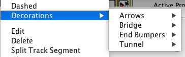
Since 4.11.4For Track Segments, there is also a Decorations item. The sub-menus provide the ability to add Arrows, Bridges, End Bumpers , and Tunnels to the track segment.
A signal head icon's popup menu allows editing of signal head information related to the panel, but also contains an Edit Logic... item that brings up a window for editing Simple Signal Logic (SSL) for the signal head. SSL supports ABS signaling, and will handle basic signal (head) logic.
Signal Mast Logic - in short SML - was added to support Aspect based signaling. It is managed using the Signal Mast Logic table. In Layout Editor, Signal Masts can be placed at Turnouts, anchor points and level crossings, but only where there is a boundary between two different layout blocks. To add a Signal Mast using a Layout Editor Panel, right click on the Turnout, level crossing or anchor point and - if a block boundary exists - you will be given the option to "Set Signal Masts..."
Refer to Logix for even more complicated logic needs not handled by SSL and SML.
With turnouts, level crossings, and anchor points, most of Layout Editor's tools for assigning signal heads to these items, for automated placement of signal head icons on the panel, and for automated creation of signal logic for the assigned signal heads may be reached by selecting Set Signals... in the popup menu. Set Signals... is not shown in the popup menu until a minimum amount of information is available to the tools. The remaining Set Signals... tools may be accessed via the Tools menu. These tools are briefly described above under Using Layout Editor's Tools Menu, and are discussed in detail on the help page of the tool's dialog pane.
In addition to signal heads and signal masts, it is possible to add sensors to block boundaries. Use the Set Sensors... item. The sensors are used to implement Entry/Exit. See Entry/Exit (NX) Routing Documentation for details.
Turnouts
Layout Editor supports eight different types of turnouts (track switches):
- right- handed (RH)
- left-handed (LH)
- wye (Wye)
- double crossover (Double X-over)
- right-handed single crossover (RH X-over)
- left-handed single crossover (LH X-over)
- single slip (Single Slip)
- double slip (Double Slip)
A three-way can be drawn using a pair of regular turnouts. Once a turnout has been created, its type cannot be changed. Changing the type of a turnout requires removing and recreating the turnout. Drawn turnout parts may be lengthened, shortened, or repositioned by dragging connection points with the meta key pressed, and the entire turnout may be repositioned by dragging the center circle with the meta key pressed.
When new turnouts (and crossovers) are created, Layout Editor uses default displacements from the center of the new turnout to "size" the new turnout drawing. Layout Editor maintains two sets of default displacements, one for for regular turnouts (RH, LH, WYE) and one for crossovers ( Double Xover , RH Xover, LH Xover). These default size parameters may be changed if a different default size is needed. First create a new turnout (or select an existing turnout) and resize it by dragging its connection points. Then select Use Size As Default in that turnout's popup menu. This will change default size parameters so that the next and subsequent turnouts to be added will be the same size as the resized turnout. Each Use Size As Default changes one of the two sets of default size parameters. Both sets of default size parameters are saved when the panel is saved. To return to Layout Editor's default turnout sizes select Use Program Default Turnout Size in the Tools menu.
Turnout drawings in a track diagram are drawn using solid lines for both continuing and diverging legs until the turnout drawings are linked to turnouts in the Turnout Table. Once linked to actual turnouts, turnout drawings show the "known states" of the turnouts they represent. After linking, you can toggle each turnout on your layout by clicking on the center point of its drawing (provided Allow Layout Control is checked in the Options menu, and your DCC system supports computer control of turnouts). The ability to toggle by clicking can be turned off by checking Disabled in the turnout's popup menu.
You can link each turnout drawing with an actual turnout (internal or hardware) in the Turnout Table as turnout drawings are created, by entering its Turnout Table name (either system name or user name) in the Turnout: Name field (top row of the tool bar) before clicking to create that turnout. Alternatively, you can create your turnout drawings first, then select Edit... in each turnout's popup menu to open an Edit Turnout dialog that allows entry of the turnout name. Once the name of an actual turnout is entered, the actual turnout can be toggled by clicking the mouse at the center of the turnout. Turnout toggling can be disabled by checking Disabled in the turnout's popup menu.
Optionally, you can designate which Block a turnout is in either by entering a block name in the Block: Name field of the tool bar prior to creating each turnout drawing, or by entering a block name in the Edit Turnout dialog at a later time. The Edit Turnout dialog also allows an Edit Block dialog to be requested, where information for the turnout's block may be entered or changed. (Blocks are discussed more fully below.)
When a side track branches from a mainline track at an RH or LH turnout, the mainline normally continues through the turnout by following the straight-through track leg (the closed path). Sometimes, however, the mainline follows the diverging leg (the thrown path). To allow entry of this information, the Edit Turnout dialog contains an entry called Continuing Route Turnout State. Continuing Route Turnout State defaults to Closed when a turnout drawing is created. You should change it to Thrown if the mainline track follows the Thrown path through the turnout. For a WYE turnout, you should always check to see if its Continuing Route Turnout State is set correctly to reflect the path of the mainline. To test if Continuing Route Turnout State is correctly set, check the state of the turnout in the Turnout Table when the turnout is set to clear the mainline. The Turnout Table state should match the Continuing Route Turnout State chosen in the Edit Turnout dialog. Defining mainline track is optional; if you are not defining mainline track this item can be ignored.
Crossover turnouts differ from other turnouts in several important ways. Like other turnouts, crossovers have two states--crossed and straight. To change a crossover's state, however, requires two or four track switches to change in unison. This may be accomplished using one to four switch machines. Normally a crossover is assigned a single turnout entry in the turnout table, but it may have several if its switch machines are controlled by different stationary decoders. (You can use two JMRI Routes controlled by the same internal turnout to make multiple switch machines work together. In this case, enter the internal turnout as the turnout linked to the crossover turnout drawing.) With crossovers, the crossover tracks are always considered side track, and any mainline track entering the turnout, leaves on the same straight as it entered. So there is no Continuing Route Turnout State entry in a crossover's Edit dialog.
If you are defining blocks through crossovers, note that crossovers have four connecting points, each of which may be connected to a different track block. So parts of a crossover may be in one, two, three, or four separate blocks. The Edit Turnout dialog for a crossover allows the entry of up to four blocks, each linked to one of the four connection points. The first block entered must be the Block: Name field; this block is linked to upper left connection point (if the turnout has not been rotated), and serves as the default block for the crossover. If any of Block 2, Block 3, or Block 4 entries are blank, the default block is used. Block connection points are numbered 1, 2, 3 and 4, proceeding from the upper left connection point in a clockwise direction.
Track Segments and Connection Points
A Track Segment is a two ended piece of track between two connection points. Connection points are found on anchor points, end bumpers, edge connectors, turnouts, slips, cross overs, level crossings and turntables.
Anchor points have one connection point that accept two connections. All other connection points only accept one. End bumpers have one connection point. An Edge Connector only accepts one connection and is used to mark the "Edge" of the current layout editor panel. Each turnout has three connection points and each slip, cross over and level crossing has four.
A connection point that can accept a connecting track segment is drawn red. When a connection point has its capacity of connections, its color is changed to green. When all connection points are green , the layout diagram is complete with all connections defined.
Track segments are normally drawn as solid lines. but you can designate that a track segment be drawn dashed to show tunnels or tracks crossing at different grades. You can request a dashed line for a track segment by checking Dashed in the tool bar before the track segment is created, or you can change a track segment to Dashed in the Edit Track Segment dialog. (More anchor points can be added to get the dashed part of your track to cover the exact area desired.) You can also designate a track segment as hidden so it's displayed only when edit mode is active. Hidden track segments are useful for track diagrams drawn as multiple rows where the end of one row connects to the beginning of the same or another row. To make a track segment hidden, check Hide Track in the Edit Track Segment dialog.
The default appearance of a track segment is a straight line however you may change its appearance to Circle, Ellipse or Bezier via its popup menu (when in edit mode). Circled track segments are drawn as fixed radius arc's connecting the two end points. When in edit mode the radius may be adjusted by dragging the center point of the circle. An ellipsed track segments end points are connected with an arc and a Bezier track segments end points are connected with a Bezier curve. Control points are used to effect the curve of Bezier track segments and may be added or deleted via the track segment's popup menu (when in edit mode).
Optionally, track segments are used to designate mainline track or side track. The legs of turnouts and level crossings are set to mainline track or side track according to the designations of track segments that are connected to them. See the discussion of continuing routes in the above section on turnouts for information on how a mainline is tracked through a turnout.
If Mainline is checked in the tool bar when a track segment is created, that track segment is designated as mainline track, otherwise it is considered side track. You can change from mainline track to side track, or vice versa, in the Edit Track dialog.
Optionally, you can designate which Block a track segment is in--either by entering a block name in the Block: Name field of the tool bar prior to creating each track segment, or by entering a block name in the Edit Track Segment dialog at a later time. The Edit Track Segment dialog also allows a Create/Edit Block dialog to be requested, so information for the track segment's block may be entered or changed. (Blocks are discussed more fully below.)
An Edge Connector is used to denote that the current track finished on this panel and can continue on another one. The connector uses the same red / green states of an Anchor point, along with a third blue state which means that the connector has not been linked with a track segment on a different panel. To do the linking, right click on the edge connector and select "edit link", the dialogue box which appears will be populated with a list of available layout panels, and any valid edge connectors. A valid edge connector is defined as one that is not already linked, is connected to a track segment that is configured with a block, which is not the same as the block our connected track segment is configured as (ie the edge connector becomes a block boundary). And that the two track segments are going in the same direction.
Level Crossings
A level crossing is a special piece of track that represents two tracks crossing at grade. A level crossing is commonly referred to as a diamond. A level crossing has four connection points, and two tracks, designated 1 and 2. When a level crossing is created, track 1 is the horizontal track, and track 2 is the inclined track. The angle between the two tracks, the incline of each track, and the length of each track may be varied by dragging connection points with the meta key pressed. The center of the level crossing may be positioned by dragging the center circle with the meta key pressed (see the help bar for which key is the meta key for your operating system).
Optionally each track will be either mainline track or side track depending on the mainline track or side track designation of the track segments connected to each track. Also optionally you may independently assign each track to a different block. If a block name is entered in the Block: Name field of the tool bar prior to creating a level crossing, that block is assigned to both tracks. Each track may be assigned to a different block in the Edit Level Crossing dialog. The Edit Level Crossing dialog also allows a Create/Edit Block dialog to be requested for each of the two blocks, so information for these blocks may be entered or changed. The block(s) assigned to a level crossing may be different from the block(s) of connected track segments; in this case, each level crossing connecting point where the block changes serves as a block boundary. (Blocks are discussed more fully below.)
Turntables
A Layout Editor turntable is a schematic representation of a turntable on the layout. A turntable is drawn as a circle with a variable number of track connections, called ray tracks. Each ray track is drawn as a short stub track radiating from the turntable circle. A track segment should connect to each ray track. Most of these track segments will connect a ray track to an end bumper. The distance of each ray track connection point from the turntable circle is fixed, but the direction of each ray track may be varied by dragging its connection point around the turntable circle. Any number of turntables may be added to a panel, and each turntable may have any number of ray tracks.
A turntable is added to a panel by selecting Add Turntable in the panel's Option menu. New turntables are placed at the center of the panel, and should be moved to desired locations by dragging its center point with the meta key pressed (right button drag on Windows). When a turntable is added, it has four ray tracks located in up, down, left, and right directions. The turntable's popup menu has two items. Selecting Edit... brings up an Edit Turntable dialog, and selecting Remove deletes the turntable and any track segments connected to it. Before a turntable is actually deleted, the program asks for verification of that action.
The Edit Turntable dialog allows the radius of the turntable circle to be changed, and provides for the addition and deletion of ray tracks. For more information on how to add and delete ray tracks, see the help page of the Edit Turntable dialog.
Backgrounds
Background images are not required for Layout Editor panels. Support for adding a background is provided for panels that require other than the default Layout Editor background. Background images may be used simply to change the color of the Layout Editor background, or for more sophisticated applications, such as setting up a CTC panel.
A background image may be created using any pixel-based image editor to create the image, and to save it as a .gif format image file. You may create a single background image for the whole panel, or create vertical slices to be used in a multi-slice background (see below). For a multi-slice background, create your slice image(s), then add copies, one to the right of the other, until the desired panel area is covered.
Important Note: if you create your own background images (or icons), don't store them with the JMRI distribution images or they will be deleted when you upgrade JMRI. Instead, create a new folder called "resources" in your JMRI Preferences directory (where your panel file is stored), and add your images and icons to that folder.
A background image is added to a panel by selecting Add Background Image... in the panel's Option menu. Selecting Add Background Image... brings up a file selection dialog for selecting the file containing the background image. Layout Editor provides for multiple background images. The first background image is placed with its upper left corner at x = 0, and y = 0. The next background image is placed at the top of the panel and to the right of right-most existing background image. This allows easy implementation of multi-slice background images (see below). The x, y location of the upper left corner of each background image is shown in it's popup menu. This location may be changed by selecting Set x & y in the popup menu.
For users building a classic US&S panel, there are two sets of predefined image 'slices' currently available. One set is 718 pixels high, and the second set is 900 pixels high. Choose the set that best fits your display. These 'slices' are located at icons/USS/background/. The 900 pixel high images include a "-9" in their names. The left and right edge images are each 12 pixels wide. The main panel 'slices' are 65 pixels wide. First add the left edge image, then add a blank slice or one including switch plate(s) for each turnout on your CTC panel, then finish by adding the right edge image. The advantages of building CTC backgrounds with slices are that 1) you can make virtually any length CTC panel, and 2) the plates will be precisely located automatically.
Blocks
Blocks are sections of track whose occupancy may be individually monitored. Dividing track into blocks is optional. Blocks set up in a track diagram normally correspond to physical blocks on a layout. Block occupancy is indicated by the state of an occupancy sensor. When a layout's track is divided into blocks, all of the track need not belong to a block. For example, yard track is normally not in a block, whereas mainline track almost always would be divided into blocks. The main use of blocks is to facilitate signaling, but blocks may be used for other layout control and animation functions.
If a block name is entered in the Block: Name field of the tool bar prior to adding a turnout, level crossing, or track segment, the added item is assigned to that block; if a sensor name (system name or user name) was entered into the Occupancy Sensor field, that sensor will be assigned to the entered block. A turnout, level crossing, or track segment may also be assigned to a block by entering that block's name in the edit dialog accessed by selecting Edit... in that items popup menu. In either case, if a block with the entered name doesn't exist, one is created.
A block name may be any series of alphabetic or numeric characters that describe the block, for example, "Red Main 2", "Lake Siding", or "Moose Block". Once a block is created, its name may not be changed; attempting to change a block's name will create a new block having the new name. After all items assigned to the old block are changed to the new block, the block with the old name will be automatically deleted (see below).
Turnout, level crossing, and track segment edit dialogs provide access to the Create/Edit Block dialog where information specific to a block may be entered or edited. The Occupancy Sensor: field in the Create/Edit Block dialog shows the name of the occupancy sensor currently assigned to the block, if there is one. To enter or change the occupancy sensor, enter the name (system name or user name) of a sensor in the Sensor Table in the Occupancy Sensor: field. A sensor may be assigned as the occupancy sensor of only one block; attempting to do otherwise will result in an error message. Normally, the state of an occupancy sensor is "Active" when a block is occupied, so "Active" for occupied sense is the automatic default. This can be changed by selecting "Inactive" in the Occupied Sense: selection box.
Block track colors are used instead of the default track color if a section of track is in a block. The track items in a block are drawn with different track colors for occupied and unoccupied states, allowing the track in a block to change color as a train enters and leaves that block. To set track colors, select the unoccupied track color in the Track Color: selection box, and select the occupied track color in the Occupied Track Color: selection box. An alternate unoccupied track color is provided for special uses. For example, Dispatcher has an option to use the alternate unoccupied track color for blocks that are allocated but unoccupied. Set the alternate unoccupied track color using the Alternate Track Color: selection box. When track color is set, Layout Editor will use the occupied track color if a block is occupied, then if not occupied, will use the alternate unoccupied track color if it has been requested, otherwise it uses the unoccupied track color.
Since blocks are items on the physical layout, the same block may be used in more than one panel. Consequently, block information is saved in the non-panel specific portion of the layout information, when panels are saved to a file on disk.
Blocks are deleted automatically when they are no longer used. Layout Editor keeps track of the number of track items (turnouts, track segments, and level crossings) that are assigned to a block. This count is displayed in the Create/Edit Block dialog as Current Use Count:. When panels are saved to disk, only those blocks with a use count greater than zero are saved.
Since 4.11.4Track Drawing Options
The appearance of the track components as drawn on the Layout Editor panel is set by the Track Drawing Options dialog.
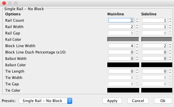
There is a column for the track defined as mainline and one for sideline trackage. Numbers can be entered using the spinners or typing in the box. The colors are set by clicking on a color box and using the color selector.
At the lower left corner is a Presets: list which can be used to select example configurations. If you customize the configuration, the panel name will be added to the presets list.
The track consists of 1 to 4 layers.
- Rail — There can be from 0 to 3 rails.
- Block — If a block has been assigned to the track component, the block layer will be drawn.
- Ballast — Simulate track ballast.
- Ties — Add ties to the rails.
The rail layer defaults to a single rail with a width of 1 for sideline and 2 for mainline.
The block line width defaults to the previous track width values.
The Block Line Dash Percentage has nothing to do with dashed track. This is a special setting to create an on/off pattern to blocks. The British 70's or Czechoslovak ČSD AŽD-71 preset uses this option.
Notes
Dashed Track — If a track segment is defined as dashed and a block has been assigned, the rail layer will not be drawn. This eliminates rail fragments that might show up in the block gaps.
Draw Unselected Turnout Leg — This option only applies to the block layer. If the rail count is 1, the rail for the unselected leg is drawn with a gap. If the option is active, the block line will also be drawn. For maximum turnout position visibliy, turn off the option.
Train Tracking
Train Tracking is an animation technique that allows us to display dynamically which train is in an occupied Block. So, for one train, or for several trains transiting a layout at the same time, we can show where each train is at any given time. Train Tracking uses the JMRI Block software. Each occupied block has a value, which is automatically passed from block to block as a train moves from block to block. A block's value is cleared when the block is no longer occupied. So the value follows the train around the layout. Setting value to a train name, passes the train name around from block to block.
Layout Editor has a built-in tool that automatically initializes each Block, creating needed Paths and BeanSettings. This initialization (previously done in scripts only) is needed to allow block software to track trains. Since Layout Editor captures the full connectivity of its panel, it has the information needed to perform this initialization. Block initialization is automatically performed when blocks are changed and when a Layout Editor panel is loaded. Since the initialization is automatic, Layout Editor users don't need to be concerned about Paths and Bean Settings.
Layout Editor allows the display of the block contents on the panel.
This might sound complicated, but it's very easy to set up because JMRI's Block and Layout Editor software does almost everything automatically. There is even software to automatically save and restore Block contents values between sessions.
If your panel has blocks assigned to the track and each block has a hardware occupancy sensor, you're ready to set up Train Tracking:
- 1. Place a Block Contents Label near each block in the panel.
- 2. Open the Block Table, and enter the name of each train in the "Value" column of the block it is occupying. Remember to click somewhere outside the value entry box after entering a train name to make Java read what was entered.
Note: If the program detects a block is unoccupied before the block's value is passed on to the next block, the train name will be lost. So it's important to have wheels and track clean, and to have enough cars in each train with current drawing wheels to ensure a block doesn't loose detection before the train enters the next block.
Tips
Since 4.10Track Level
The Layout Editor track components are drawn at level 3. Icons are drawn at level 10 and labels are drawn at level 4. These can be placed over track components. Depending on opacity, the track will be hidden. To make the track appear over the icon or label, change the icon or label level to 2. This replaces the old trick of using hidden track segments.
Panel Differences
Since Panel Editor panels are fully icon based, their track schematic has the possibility of looking more prototypical. Layout Editor panels have more animation possibilities and automated tools for setting up signals, train tracking, etc. If you would like both worlds, consider building both Panel Editor and Layout Editor panels for your layout. You can switch between them easily using the Panels menu. Since both type of panels share the same configuration items (turnouts, sensors, memory variables, block contents, signal heads, etc.), whatever is set in one panel is reflected in the other if the same items are displayed. After they are loaded, panels continue to function, whether they are displayed or not-- they just need to show up in the Show Panel submenu. So, for example, if you set up a Layout Editor panel for train tracking as described above, you can track trains in a companion Panel Editor panel just by adding Block Contents Labels or follow a bunch of sensors using a dedicated Switchboard.
Putting Finishing Touches on your Panel
Below is an enhanced version of the simple oval panel constructed in Getting Started with Layout Editor. The general steps needed to get from that starting panel to this panel are sketched below. The steps need not be done in the exact same order presented. The presented order works, but variations are possible to get to the same end point. This example is presented to illustrate some of the things that can be done easily using Layout Editor. You may elect to do more or less on your Layout Editor panels.
- Turnouts from the Turnout Table were assigned to each turnout graphic using the Edit... item in each turnout's popup menu.
- Three new anchor points were added-one on each side vertical track, and one on the bottom track to serve as block boundaries. Block boundaries are places on the track where two blocks join; track at a block boundary is normally gapped on the physical layout. Adding anchor points was made easier by using the Translate Selection... tool in the Tools menu, to spread out the original panel in the vertical and horizontal directions.
- Layout track was divided into blocks by assigning block names to all track segments and turnouts. When a block name is entered, if a block by that name doesn't exist, a new block is automatically created. Turnouts were placed in the same block as the track segment connected to their throats (facing points), and track segments connecting to turnout continuing and diverging points were placed in different blocks.
- Block names were placed on the panel using Text Label on the toolbar. This was done for this illustrated example, but you may or may not want to display block names on your final panel.
- Each block was assigned an occupancy sensor from the Sensor Table. Sensors were added to the Sensor Table prior to assigning occupancy sensors. An occupancy sensor was assigned to each block using the Create/Edit Block button in the Edit Track Segment dialog of one of the track segments in the block.
- Track on the main oval were designated mainline track using the Edit Track Segment dialog for each track segment. This gave different track widths for mainline and side track.
- Signal Heads were defined in the Signal Head Table for each of the signals to be placed on the panel. Triple Output signal head types were used for all.
- Signals Heads were placed at turnouts using the Set Signals at Turnout tool in the Tools menu. For each signal head Add Signal Icon to Panel was checked, but Set up Logic was not.
- Signal Heads were placed at block boundaries at the three anchor points using Set Signals at Block Boundary in the Tools menu. Add Signal Icon to Panel was checked, but Set up Logic was not.
- Logic for the signal heads at turnouts was set up using Set Signals at Turnout. The name of the turnout was entered, then Get Saved was clicked to retrieve the turnout names. Next Set up Logic was checked for each signal head, and Add Signal Icon to Panel was not.
- Logic for signals at anchor point block boundaries was set up using Set Signals at Block Boundary by following a similar procedure.
- Since all signal heads will show red if occupancy sensors are in an "Unknown" state, the Sensor Table was opened and all occupancy sensors were set to "Inactive" (unoccupied) by clicking "Unknown" once. Then the industry turnout was clicked to set it to thrown, producing the panel shown above (with Edit Mode switched off in the Options menu).
You should be able to toggle your turnouts by clicking at their centers and watch your signal heads change color. If you don't have hardware yet for your occupancy sensors, you can change their state in the Sensor Table to simulate a train moving on the layout. (Or you could set up Sensor Icons and click on them to change their state.) If any of the above steps are not clear, consult the description of that item in the documentation above. The help page for each referenced tool also contains explanatory information about that tool.
This is an example of what can easily be done using Layout Editor. For those planning to install signal heads, setting up a panel with blocks defined and signal heads placed can help in deciding where blocks and signal heads/masts should be placed before actually installing them on your layout.
Back to the PanelPro help page.
Thanks and congratulations to all who contributed!
Copyright © 1997 - 2018 JMRI Community.
JMRI®, DecoderPro®, PanelPro™, SignalPro™, TrainPro™, DispatcherPro™, OperationsPro™ and associated logos are our trademarks.
Additional information on copyright, trademarks and licenses is linked here.
Contact us via the JMRI users Groups.io group.
Site hosted by:
![]()
See also the site status page.