JMRI: PanelPro
The JMRI libraries contain the PanelPro application for creating control panels. This page describes the application, and how to use it.PanelPro provides four separate ways to create Control Panels:
- The Panel Editor lets you graphically draw a Panel exactly the way you want it, and then animate parts of it to show the status of your layout and let you click to control it.
- The Control Panel Editor works like Panel Editor but provides an alternative interface.
- The Layout Editor provides tools to make a smart schematic of your layout while constructing the logic for signals, etc. This constrains how the panel appears a little, but it can save significant time when first bringing your layout up.
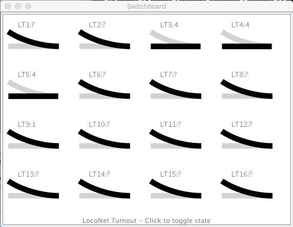
- Switchboard Editor is a graphic, straightforward control interface, showing a range of switch keys to watch and control items.
Which to use: Layout Editor or Panel Editor?
The Layout Editor builds a "Layout" which is a logical description of your entire layout. You only have a single Layout, otherwise it is not possible for the software to connect track elements together across the boundaries between multiple Layouts. A Layout, built with the Layout Editor, can be used for directly controlling elements such as Turnouts and Signals; indeed many users find it very suitable for this task. But, it is primarily designed for automation and semi-automation within JMRI. For example, you can use the Layout Editor to construct a description of your track and its blocks and signals. The software can automatically work out how to set your signals based on the position of turnouts and whether blocks are occupied, and the rules appropriate to your railroad (ie. select the signal rules based on different company practices!, and no need to know how to create the rules to link your signals to the state of turnouts, blocks and other signals !). Layout Editor Panels may also be used to set up automatic running of trains on your layout using Dispatcher. In addition, the Layout description of your railway can be used by scripts such as the included AutoDispatcher2 to automatically control your trains. There are many other tools within JMRI which require a description of your railroad and the description comes from the Layout built in the Layout Editor. The Layout Editor has many rules built into it about how track is connected, the naming of blocks, etc.. In order to function, there are constraints on the appearance of track elements and how they are used.
The (Control) Panel Editor builds graphical control
Panels. You can have as many Panels as you like, covering as
much or as little of your railway as you like, with overlaps
in area or functionality if required. Panels might be
diagrams showing the state of the track and signals, or they
might be prototypical signaling and dispatcher panels. Or
anything else you find useful to control your railroad; you
have total flexibility over their appearance. There are
several standard graphics sets distributed with JMRI, but it
is often necessary to make some of the elements in an
external graphics package to be imported as GIF or PNG files.
These might include the Panel Background, or the icons to attach
to active elements (switches, levers, track state, signals,
etc.) which are then placed on the Panel.
Control Panel Editor supports using
Warrants and automatic running of trains.
 Many people use
both, with the Layout Editor creating schematic panels to
handle the actual configuration for signals and Panel Editor
providing exactly the appearance desired. For example, Bob
Bucklew has prepared a three part tutorial
that describes how Panel Pro and Layout Editor can be used
together.
Many people use
both, with the Layout Editor creating schematic panels to
handle the actual configuration for signals and Panel Editor
providing exactly the appearance desired. For example, Bob
Bucklew has prepared a three part tutorial
that describes how Panel Pro and Layout Editor can be used
together.
The Switchboard is easier to set up, using a simple grid of pre-defined buttons or indicators. It is limited to the basic inputs (Sensors) and Outputs (Turnouts and Lights).
Please see our Gallery page for examples of how model railroaders have used this on their own layouts. There's also an example of using PanelPro for modular layouts.
Rodney Black's CATS application is another tool for creating modern-style Control Panels.
The Panel Editor
With the JMRI Panel Editor, you can make a control panel look and operate any way you want.
A panel is one or more background pictures, on which are drawn icons to represent Turnouts, Sensors and Signals on the layout. You can build the background from small icons (as in the image above left), or provide a detailed drawing that you created in a drawing program (image above right).
You can use these tools to configure quite complicated panels for large layouts. The example above is from Nick Kulp's Cornwall Railroad. There's a page on the main web site that describes this in detail. There's also a page describing the panel for Kent Williams's Oregon Washington Navigation & Railway. Robert Bucklew's Quaker Valley Lines is also building a CTC panel using PanelPro. (This is a second generation panel with some advanced features; there's also a page describing the older, simpler panel)_
Also, refer to the signaling page for information on adding logic to operate the signals on your layout under the control of your panel.
Panel operation
Clicking on a turnout symbol flips it from closed to thrown and vice-versa. A turnout also has "unknown" and "inconsistent" states, represented by an icon with a question mark and X respectively. These represent a state where no information has been received, and where the information is internally inconsistent (e.g. both closed and thrown at the same time).This control can be used in various ways. For example, you could have a turnout icon covering a turnout on a schematic diagram. When you click on it, the turnout on the layout would be commanded to change, and the track diagram would show which way a train would be routed. Or you could use icons that show a lever to the right or left, and create a panel that looks like a traditional US&S panel.
"Sensors" can be used to represent occupancy indicators or other inputs. The default icon is a small circle, with color used to represent the state of the sensor. These respond to changes on the layout automatically. Clicking on a sensor causes the sensor to alternate between "active" and "inactive" states. With the default icons, active is a green circle and inactive is an empty circle. These are meant to represent a lit/dark panel indicator. A red circle represents the "unknown" state, used when no information has yet been received from the layout.
Creating a panel
These are made with a "Panel Editor", which allows you to place images to represent turnouts, sensors (on some systems) and trackwork.The rest of this page gives you a walk-through of the process. If you'd like to see animated clinics that show how each of these things are actually done on the computer screen, please see Dick Bronson's clinics page.
You start the editor by selecting "New Panel..." then
"Panel Editor" from the "Panels" menu on the main window.
You'll get a blank control panel, plus the editor window:
From the top, this contains:
- Two text fields specifying where (in pixels) new components will be inserted on the panel. You can generally ignore these, as once the components has been inserted you can drag it around by holding the meta (Apple, command, etc) key down.
- A button to pick a background image. The editor's drawing capability is rudimentary and likely to stay that way for a long time. To create CTC panels, complex track diagrams, etc, its easier to draw them in some other program and insert them as the background image for a JMRI control panel.
- A button to add a text label. Put the desired text in the field and click the button. You can slide the label around after inserting it, but you currently can't edit the text later.
- A button to add an icon as a label. This is a way to
add track symbols, etc. To select the icon, click the "edit
icon..." button to pop an icon editor panel.
The current icon is shown at the top. To change it, use the tree in the bottom of the window to select a new one, then click on the icon at the top of the icon editor panel to load the selected icon. This is a general mechanism: Any icon on an icon editor window can be replaced by selecting the desired new one and clicking on the icon to be replaced. - Two sections for adding left- and right-bound turnouts. These actually work the same way, only with different icons to represent the states of the turnouts. Enter the turnout number (e.g. 23) and click "Add turnout:". If you'd prefer a different graphic for the closed and thrown states, you can change their icons as described above.
- A section for adding a sensor. Type the sensor number (e.g. 74) in the field and click "Add sensor:".
After getting the Panel the way you want, you can use the "Store panel..." entry in the "Panels" menu to write it to an .xml file. More information about the JMRI Configuration Files
Available Icons
The JMRI library contains lots of contributed icons for representing CTC panels, LEDs, etc. You can browse through them with the tree in the bottom of the editor frame. Perhaps the best way to see what each looks like is to select it in the tree, then click on the icon next to the "Add icon" button. That will load it.You can also create your own icons and use them by selecting from the "file" section.
For little bits of track, e.g. to connect turnouts, you might want
resources -> icons -> small schematics ->tracksegmentsthen block.gif, etc.
We do need to do a better job of organizing the available icons!
Manipulating Icons
To move an icon around on the panel, you "meta-drag" it. On a Mac, that's "hold the cmd key and drag with the cursor"; on windows, it might be the Windows or control key. Or it might be a right-drag. Sorry, I don't have a Windows machine here to figure it out.There's also a pop-up menu (ctrl-click on a Mac) that will provide various ways to manipulate the icon. It will let you rotate the icon so that it points in whatever direction you want. Text labels can have their font, size and color changed. You can also remove icons from the panel with the popup menu.
Other types of panels
Because this is icon-based, you can create panels that look any way you want. For example, instead of using track-schematic icons for turnouts, you could use small images of the levers and plates on CTC machine. This would give you "mechanical" levers you can flip back and forth with a click. This can be made absolutely prototypical, or can be simplified for easier and faster operation, as you prefer.It's also possible to create a panel where the "track" lines change color to indicate whether the track is occupied. The procedure for doing that is described on a separate page.
The Control Panel Editor
Control Panel Editor is simply an alternative view and controller with the same content data as Panel Editor. Control Panel Editor allows you to edit a Panel using menus instead of a separate editing window.
For more information, see the Control Panel Editor help page.
The Layout Editor
 The Layout
Editor helps you create simple schematic panels, while
simultaneously setting up the block and signal logic needed
to operate the layout. Its strength is its ability to capture
how the tracks are connected, where each block is located and
how each signal is related to blocks. On the other hand, it
provides only limited ability to customize how the panel
appears.
The Layout
Editor helps you create simple schematic panels, while
simultaneously setting up the block and signal logic needed
to operate the layout. Its strength is its ability to capture
how the tracks are connected, where each block is located and
how each signal is related to blocks. On the other hand, it
provides only limited ability to customize how the panel
appears.
 You edit via
"Edit Mode", which makes the connections between elements and
the layout visible (See figure to the right). For example,
you can click on the circle in the middle of a track segment
and select the associated occupancy detector (Sensor) on the
layout. Once you've done that, the color of the track segment
on the screen will change when the track is occupied. You can
configure the colors used, the width of the track lines, and
other details of the presentation.
You edit via
"Edit Mode", which makes the connections between elements and
the layout visible (See figure to the right). For example,
you can click on the circle in the middle of a track segment
and select the associated occupancy detector (Sensor) on the
layout. Once you've done that, the color of the track segment
on the screen will change when the track is occupied. You can
configure the colors used, the width of the track lines, and
other details of the presentation.
The Switchboard Editor
Switchboards provide a visual control grid for your JMRI layout "out of the box".
To create a new Switchboard, from the Panels menu, choose New Panel >
Switchboard Editor.
For more information, please see the Switchboard Editor help page.
Communicating with Multiple Systems
PanelPro can communicate with more than one layout control system. For example, the Cornwall Railroad mentioned above uses C/MRI hardware for sensing the status of blocks and turnouts on the layout, but drives turnout positions through a Digitrax DCC system.
To configure the program to talk to multiple systems, add both in JMRI Preferences using the + tab on the Connections pane. For more information, see the Preferences panel Help page.
If you add a turnout, sensor or signal to a panel using just a number, e.g. "23", it will be assigned to the first system on the Preference panel. To access the 2nd system, you have to use JMRI System Names. For example, if the second attachment is to a LocoNet system, you'd refer to a LocoNet Turnout as LT13; a LocoNet sensor as LS21, etc. See the page on Names & Naming for more information.
Thanks and congratulations to all who contributed!
Copyright © 1997 - 2018 JMRI Community.
JMRI®, DecoderPro®, PanelPro™, SignalPro™, TrainPro™, DispatcherPro™, OperationsPro™ and associated logos are our trademarks.
Additional information on copyright, trademarks and licenses is linked here.
Contact us via the JMRI users Groups.io group.
Site hosted by:
![]()
See also the site status page.