JMRI Hardware Support: MERG CBUS Main Support Page
JMRI Documentation
As support for MERG CBUS continues to evolve, this is not a definitive MERG CBUS network guide.
These JMRI user guides contain considerable simplification of the MERG CBUS scheme, and are aimed at helping new users to JMRI or MERG CBUS, not systems developers.
The latest developers guide and full specification is held on the MERG CBUS wiki hosted by MERG.
JMRI MERG CBUS Support Pages
- JMRI MERG CBUS Support This Page
- Naming events in JMRI
- Connection Details - MERG CAN connection options in the main JMRI preferences.
- JMRI CAN Support
- JMRI Scripting for CAN frames ( jython )
JMRI MERG CBUS Tools Support Pages
- Console - Tool for viewing and sending CAN frames / events.
-
Event Table - Monitors events and presents them in a table full of statistics.
- Event Statistics On / Off / In / Out
- Table Import and Export
- Node Config Tool - For MERG CBUS node configuration and editing Node Variables.
- Command Station Monitor - Loco session monitoring and Command Station Tools.
- Send Frame - Send CAN frames or MERG CBUS events
- Sequencer Send a sequences of event frames in a loop
- Event Capture Tool - Capture MERG CBUS events
- Event Request Monitor - Request Event status monitoring tool
- Network Item simulation - Simulates Cbus Command stations and responds to event requests
Connecting
Typical first-time Connection Steps
- Many Modern Operating Systems do not require device drivers to be installed
when connecting a MERG CANUSB4 to a computer.
Plug in, and check that no major error messages appear. - Install JMRI
- Connection Preferences - Select MERG connection,
use "CAN via MERG CAN-RS or CAN-USB" for a CANUSB4 with default settings.
You could also choose CAN Simulation if you have no physical connection to a MERG CBUS network. - Save / Restart JMRI
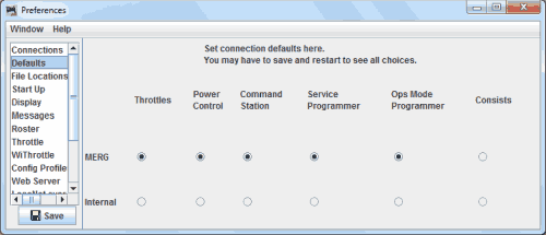
- If you are using DCC over the MERG connection, check that JMRI Preferences > Defaults
are set correctly, see DCC over MERG CBUS.
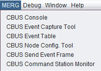
Restart JMRI a few times, checking that the default connection preferences have stuck. - A new menu item MERG appears in the PanelPro or DecoderPro window, containing the MERG tools.
Help > Window Help will show relevant info in the tools and any JMRI window. - Test events can be sent from the MERG Send CAN Frame tool.
Set the test event, eg Frame packets "+1" and / or "-2" ( without the quotation marks ), waiting 500 msec and click Start Sending to generate steady MERG CBUS network traffic.
Check that these events are actually being sent over the MERG CBUS network by using a module such as a CANACT. - Use an external producer module to test connectivity receiving events, confirming they appear in the MERG CBUS console.
- The JMRI System Console is a good tool for diagnosing issues during setup and operation.
MERG CBUS Events
MERG CBUS events are transmitted as a one-to-many network,
connected modules receive all network data then choose whether or not to act on them.
This enables multiple modules to act on a single event, eg :
- A physical turnout ( UK - point ) microswitch sensor is wired to a
MERG CBUS producer module .
The module has been taught to send a particular event when the switch is closed. - This event is received by a relay driver ( consumer ), which changes the frog polarity.
- The event is also received by an LED module which has not been taught the event, so does nothing.
- The event is also received by an LED module ( consumer ), lighting a LED on a mimic panel.
- The event is also received by JMRI ( consumer )
- A JMRI sensor has been created with the event number,
causing the sensor status to change
A JMRI turnout ( point ) has its turnout feedback set by this sensor.
JMRI panel(s) update to reflect the new point position. - JMRI Signalling Logic recalculates, and on the JMRI panel, a signal protecting the point changes from Red to Green.
- The JMRI Signal Mast mapping is checked and the relevant MERG CBUS event is sent to change that on the layout ( producer )
- This event is received by a LED ( or servo ) module which changes a physical on-layout signal ( consumer )
- This event is also received by a LED module which changes a signal on a mimic panel ( consumer )
- A train, controlled by ( JMRI DispatcherPro for a JMRI Layout Editor Panel ) or (
JMRI Warrants for a JMRI Control Panel Editor panel ),
sees that the signal ahead has cleared and can increase its speed.
DCC commands are generated from JMRI and sent over MERG CBUS using special events ( producer ) - These MERG CBUS events are received by a MERG CANCMD ( consumer ),
which then sends the actual DCC command out to the track or boosters.
This train had requested the section ahead of it, JMRI Dispactcher/Warrants had allocated it ( after checking occupancy and other rules ), then sent the turnout event ( producer ) to change the points.
The event was received by a Servo or solenoid module ( consumer ) which had triggered correctly, changing the point sensor right at the top of this example.
- You can start small and think big,
adding more modules as your time and experience allows.
Many people use MERG CBUS and JMRI purely for displaying turnout positions, adding things like track occupancy, on-layout signals, mimic panels etc. at a later date.
If you anticipate adding track occupancy, especially track circuit electrical block ( Train On Track Indicators ), ideally plan the electrical scheme for this on your layout at any early stage.
MERG CBUS events generally come in two types: "ON" and "OFF".
Events can be short ( SLiM ) events, eg +11 for event 11 on.
Events can be long ( FLiM ) events, eg -N2E7 for node 2 event 7 off.
JMRI, being both a consumer and producer of events, can send and receive on any node number and any event.
Adding events to JMRI
MERG CBUS events are stored as
- JMRI Sensors ( Inputs )
- JMRI Turnouts ( Outputs )
- JMRI Lights ( Outputs ).
These are accessed via JMRI Tables, ie PanelPro > Tools > Tables > (
Sensors,
Turnouts or
Lights ) .
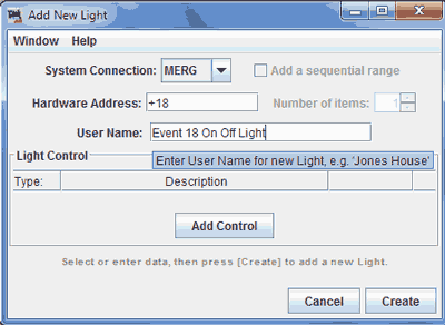
When the table loads, click on " Add... " button at bottom left to create an item.
For most short events, you just need to enter the number. Here's a few examples :
| Hardware Address | Meaning | Event Consumed as Sensor |
Event Produced as Turnout |
Event Produced as Light turned |
|---|---|---|---|---|
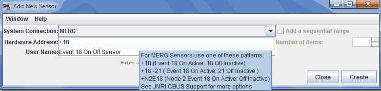
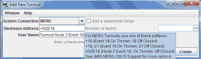
+18 |
Event 18 On
Event 18 Off |
Sets sensor Active Sets sensor Inactive |
Thrown Closed |
On Off |
+18;+21 |
Event 18 On
Event 21 On |
Sets sensor Active Sets sensor Inactive |
Thrown Closed |
On Off |
+18;-21 |
Event 18 On
Event 21 Off |
Sets sensor Active Sets sensor Inactive |
Thrown Closed |
On Off |
+N2E18 |
Node 2 Event 18 On
Node 2 Event 18 Off |
Sets sensor Active Sets sensor Inactive |
Thrown Closed |
On Off |

You will need to enter the Hardware Address in a JMRI recognised format to create the event.
If the create button is grayed out, check your hardware naming format.
Adding a User Name ( using any characters ) when creating a table item may make accessing it easier in JMRI.
Remember to save your tables!
For more on events, see JMRI system naming with MERG CBUS.
DCC over MERG CBUS
DCC is not a requirement for MERG CBUS or JMRI. Many DC layouts use MERG CBUS + JMRI for route setting, signalling and track occupancy purposes.
JMRI will send the DCC events over the MERG CBUS network and can be monitored within the MERG CBUS console
The MERG system allows for advanced consisting to be set using CANCMD and CANCABs.
JMRI Consisting : Advanced Decoder Consisting ( Decoder Assisted Consist) is currently unsupported, hence this is set to Internal.
Primary Address Consists are supported however.
Connecting a MERG DCC Command Station CANCMD
Make sure that main JMRI Preferences Defaults are set to your MERG connection for Throttles, Power Control, Command Station, Service Programmer and Ops Mode Programmer.
Although the CANCMD supports Advanced Consisting, this has not been implemented within JMRI at present.
You can use an existing DCC command station, or have a separate DCC command station for a programming track ( eg. a Sprog ) by setting these options.
Events do not need to be set up to connect a MERG DCC Command Station CANCMD.
DCC Accessory Decoders can be controlled over MERG CBUS and a CANCMD by creating turnouts with explicit RDCCx Opscode commands,
see MERG CBUS hex event naming.
This is also discussed within the MERG CBUS WIKI documentation.
Programming Train CV's
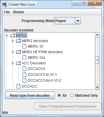
Program train CV's using DecoderPro
CANCMD fully supports DCC CV programming.
There are definitions within DecoderPro for the MERG CANACC5 .
Signalling
There are multiple ways to interface JMRI signalling with MERG CBUS modules.
You are strongly advised to let JMRI control your signal logic, however it's also possible to link JMRI with 3rd party signalling over MERG CBUS.
JMRI includes various UK signalling definitions, a popular choice being BR2003, however for some layouts LMS 1932 or GWR 1931 may be more appropriate.
Once you've got basic signalling setup, you can customise your layout with things like
the UK East Coast Main Line flashing green aspects.
Add JMRI Logix to listen for the correct conditions to display the aspect and send events to the layout.
Sending JMRI Controlled Signal Logic to your layout
There are multiple ways of sending cbus events from JMRI out to LED or servo signal control modules, this is just one approach.
- Add all aspects to the signal in question to the Turnout Table, eg
Signal1Red : Hardware address :+N256E412( Set Node to whatever your JMRI node is, only uses the ON event )
Signal1Flashing Precautionary : Hardware address :+N256E416
Signals which can only display 2 aspects ( eg a Servo controlling a semaphore signal ) can be setup with 1 MERG CBUS event, using the ON and OFF status, eg Signal5RedGreen :+N256E418;-N256E418. - It's also worth creating an internal turnout named something like DummySignalOutput.
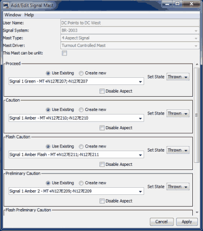
You can use this output for signals which have not yet been installed with CAN events but may have in future. - Add the Signal Mast via the Signal Mast Table
- Specify type : Turnout Controlled
- Specify which turnout ( aka JMRI message output ) you wish to show to show for each aspect, eg. Signal1Red Thrown.
- For virtual signal masts which are not yet physically installed on your layout, use the DummySignalOutput internal turnout created earlier.
With this approach, you can easily add and edit which MERG CBUS events are sent from a JMRI controlled signal without editing or re-creating the underlying signal logic.
It also ensures that only 1 MERG CBUS message is sent for flashing aspects,
specify this flashing in the module board, not JMRI!
Some Signal Mast types send 1 MERG CBUS message for each flash.
A layout with 20 quad aspect signals could send 40 odd cbus events every 0.5seconds, 4,800 events per minute.
This could make network diagnosis awkward, although very unlikely to swamp a MERG CBUS network.
As stated previously, this is just one approach. There are may ways of interfacing JMRI with MERG CBUS signalling systems.
Receiving Module supplied or existing Signal Logic into JMRI
This is normally done the other way round, however people may have existing systems in place which they do not want to change.
- Create a virtual Signal Mast, named something like SignalMast7
- Create incoming MERG CBUS event(s) as sensor(s), eg "SignalMast7Red".
- For each signal state ( eg. Stop or Proceed ),
create a new JMRI Logix
in the JMRI Logix Table to set the signal head or mast as appropriate, similar to
If SignalMast7Red is active, set SignalMast7 to Stop - Repeat for each signal state
Third Party / Support
- https://www.merg.org.uk/merg_resources/cbus.php The Model Electronic Ralway Group MERG CBUS introduction page.
- https://www.merg.org.uk/merg_wiki/doku.php?id=public:cbuspublic:start The Model Electronic Ralway Group MERG CBUS Wiki with full protocol specification.
- https://www.merg.org.uk/merg_resources/cbus-dcc.php The Model Electronic Railway Group MERG-DCC help page.
- https://www.merg.org.uk/kits.php
MERG CBUS kits. Constructing kits may not be an easy task for all, it requires a
certain amount of technical ability, and foremost the willingness to learn.
Classic refers to a 15v AC kit power supply ( most easily adaptable for 12v DC ), 2G are all 12v DC kits.
Classic and 2G modules can both be on the same network with an element of care, seek further advice if in any doubt, do not guess!
Reliabiliy soldering MERG kits together may not be the best cbus route for all. If you are in the least bit impatient, you may be better suited to a commercial offering.
If you wish to learn about electronics and their application in a model railway environment however, the member resources available are many and varied! - Please ask for help by other JMRI Users at Groups.io, or if a MERG member on the very active MERG members forum.
- For extra logging while debugging, locate and edit the default.lcf file
in the root of the JMRI install, see the pattern at the end of the file.
General MERG CBUS logging - log4j.category.jmri.jmrix.can.cbus=DEBUG
Connection logging - log4j.category.jmri.jmrix.can.adapters.gridconnect=DEBUG
The extra logging will appear in the JMRI console, also the JMRI error logs. - https://github.com/JMRI/JMRI/issues?q=is%3Aissue+is%3Aopen+merg
Current known ( open ) issues relating to MERG by the JMRI developers on Github.
Github is not a support tool. - https://github.com/MERG-DEV MERG CBUS Development on Github - Much of it is licensed under the GNU General Public License v3.0.
- https://github.com/phillipsnj/mergCbusServer MERGCBUS Server - enables multiple network connections to a MERG CANUSB4 using Node.js , MIT License.
- https://github.com/amaurial/mergCanBus MERG CBUS implementation for Arduino. ( + have a look at Amauria's other MERG CBUS Github projects )
- http://www.oscale.net/?q=en/cbus MERG CBUS on an Arduino using CAN BUS shields - See download links at bottom ( in English + German )
- https://www.npmjs.com/search?q=keywords:MERG node.js modules to create a MERG CBUS module + Class to create a MERG CBUS module conneted via ethernet.
- http://www.rickdavis.co.uk/rail/control-cbus.php Middle Earth Model Railway has over 70 MERG CBUS modules installed on it and uses JMRI.
Originally named CBUS by co-founder Gil Fuchs, MERG CBUS isn't a MERG
project and is "open source" or public domain.
In 2007, when the scheme was being developed, MERG had a website willing to host the project
and organised the kits ( many designed by the other MERG CBUS co-founder Mike Bolton ).
The scheme is now called MERG CBUS to avoid conflict with a home automation
system which has trademark on a similar name.
MERG CBUS co-founders : Gil Fuchs, Mike Bolton
Mike Bolton designed hardware and coded firmware for many of the initial modules, lead for CAN-RS module and code
The standalone MERG DCC programmer was the inspiration behind the popular SPROG DCC programmer, which is fully supported in JMRI.
Andrew Crosland has been heavily involved with JMRI through both SPROG and MERG CBUS,
writing much code to enable JMRI to support MERG CBUS.
Anything to do with CANUSB, CANUSB4 and Gridconnect etc, he's an expert!
Andrew also he wrote the MERG CANCMD code and designed the MERG CANUSB4
Kevin Dickerson was instrumental in writing the original JMRI to MERG CBUS interfaces, supported by Andrew.
Pete Brownlow has updated the CANCMD firmware, also lead for the CANEther module, and the MERG JMRI go-to person!
Amauri Albuquerque has been the main SW writer for the CANPiWi
( based on the RPi Zero W and is an interface between ED/ WiThrottle and CBUS ), and CANPi.
CANPi is a version of this for a RPi 3B ( with Ian Hart's CAP.)
Ian Hart designed the Pi CAP, also the popular CANMIO range of modules.
Roger Healey is also key to the MERG CBUS success story being lead developer on the FCU, a Windows configuration utility for setting up FLiM modules ( independent of JMRI )
N J Philips established the mergCbusServer and keeps it up to date.
The MERG kit elves who package the kit parts are amazing, having enabled thousands of MERG CBUS module kits to be sent out to members.
The JMRI developers do a fantastic job of keeping updates flowing, making JMRI easier to use on each release :-)
Apologies to anyone missed out or inaccuracies, let us know and I'll gladly edit the page! - SY
Thanks and congratulations to all who contributed!
Copyright © 1997 - 2018 JMRI Community.
JMRI®, DecoderPro®, PanelPro™, SignalPro™, TrainPro™, DispatcherPro™, OperationsPro™ and associated logos are our trademarks.
Additional information on copyright, trademarks and licenses is linked here.
Contact us via the JMRI users Groups.io group.
Site hosted by:
![]()
See also the site status page.